


4-2-7 TROUBLE LEVEL OF SYSTEM
<< System Condition when Outdoor Unit Error is occurred >>
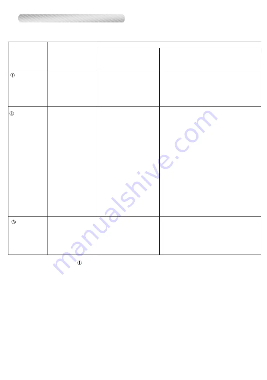
Not indicated on Indoor Unit and
Peripheral unit.
Indicated on Service Tool.
Indicated on Indoor Unit (*1)
and Peripheral unit.
Indicated on Service Tool.
Abnormal LED indication
Outdoor unit does not stop
Operation continues
- 14.1 Outdoor unit network
communication 1 error
- 13.1 Communication error between outdoor unit
- 14.2 Outdoor unit network communication 2 error
- 14.5 The number of indoor unit shortage (*2)
- 61.5 Outdoor unit reverse phase, missing phase wire error
- 69.1 Outdoor unit transmission PCB parallel communication error
- 9A.1 Coil1 (Expansion valve1) error
- 9A.2 Coil2 (Expansion valve2) error
- 9A.3 Coil3 (Expansion valve3) error
- A5.1 Low pressure abnormal (*3)
System Condition
Outdoor unit Condition
System is not
stopped compulsorily
Trouble Level
1
2
(*1) This will not be displayed on indoor unit which Error Report Target (function setting 47 of indoor unit) is set "for administrator".
(*2) The System condition can change to (Trouble Level 1) by changing DIP SW (SET 4-1:OFF)
(*3) Even if power is reset, this Error cannot release. In Error release, you need to solving the problem and operate the push switch and a and apply
"Error reset" (F3-40) after power restart.
(*4) When one of outdoor unit on the multi connection detects these Error, the backup operation can activate by using of remaining outdoorunit(s)
Please check each trouble shooting, and read the caution before using the backup operation.
- 62.3 Outdoorunit EEPROM acccess error
- 62.8 EEPROM data corrupted error
- 73.5 Heat Ex.1 liquid temp. sensor error
- 73.7 Heat Ex.2 liquid temp. sensor error
- 75.1 Suction gas temp sensor error
- 82.2 Sub-cool Heat Ex. gas outlet temp. sensor error
- 83.1 Liquid pipe temp. sensor 1 error
- 83.2 Liquid pipe temp. sensor 2 error
- 62.6 Inverter communication error
- 63.1 Inverter error
- 68.2 Rush current limiting resister temp. rise protection (*3)
- 71.1 Discharge Temp sensor 1 error
- 72.1 Compressor Temp sensor 1 error
- 73.4 Heat Ex. 1 gas temp sensor error
- 73.6 Heat Ex. 2 gas temp sensor error
- 74.1 Outdoor Temp sensor error
- 77.1 Heat sink Temp sensor error
- 84.1 Current sensor 1 error (*3)
- 86.1 Discharge pressure sensor error
- 86.3 Suction pressure sensor error
- 86.4 High pressure switch 1 error
- 93.1 Inverter compressor start up error (*3)
- 94.1 Trip detection (*3)
- 95.5 Comp. motor loss of synchronization (*3)
- 97.1 Outdoor unit fan motor lock error (*3)
- 97.5 Fan motor temperature abnormal (*3)
- 97.9 Fan motor driver abnormal (*3)
- A1.1 Discharge temperature 1 abnormal (*3)
- A3.1 Compressor1 temperature abnormal (*3)
- A4.1 High pressure abnormal
- A4.2 High pressure protection1
- A6.3 Outdoor Heat Ex. 1 gas temp. abnormal (*3)
- A6.4 Outdoor Heat Ex. 2 gas temp. abnormal (*3)
- AC.4 Heat sink temperature abnormal
- 67.2 Inverter PCB short
interruptation detection
Abnormal LED indication
Outdoor unit stop
System is
compulsorily stopped
(*4)
<< Error code which manual error release will be required >>
A5.1 Low pressure abnormal
84.1 Current sensor 1 error
93.1 Inverter compressor start up error
94.1 Trip detection
A1.1 Discharge temperature 1 abnormal
A3.1 Compressor 1 temperature abnormal
97.1 Outdoor unit fan motor lock error
97.5 Fan motor temperature abnormal
97.9 Fan motor driver abnormal
68.2 Rush current limiting resister temp rise protection
95.5 Compressor motor loss of synchronization
A6.3 Outdoor heat exchanger 1 gas temperature abnormal
A6.4 Outdoor heat exchanger 2 gas temperature abnormal
System is
compulsorily stopped
Abnormal LED indication
Outdoor unit stop
04-08
Summary of Contents for Airstage UTP-RU01AH
Page 1: ...SERVICE MANUAL 208 230V 60Hz ...
Page 5: ...1 TEST RUN ...
Page 6: ......
Page 34: ...2 OUTDOOR UNIT OPERATION CONTROL ...
Page 59: ...3 INDOOR UNIT OPERATION ...
Page 60: ......
Page 82: ......
Page 83: ...4 TROUBLE SHOOTING ...
Page 84: ......
Page 186: ...04 96 0 24 AOUA120 208 230 AOUA72 90 0 19 RED WHITE BLACK U V W ...
Page 208: ...5 APPENDING DATA UNIT ...
Page 209: ......
Page 215: ...CASSETTE TYPE MODELS AUUB18TLAV AUUB24TLAV AUUB30TLAV AUUB36TLAV 05 06 ...
Page 217: ...MEDIUM STATIC PRESSURE DUCT TYPE MODEL ARUM24TLAV 05 08 MODEL ARUM30TLAV ARUM36TLAV ...
Page 218: ...HIGH STATIC PRESSURE DUCT TYPE MODELS ARUH36TLAV ARUH48TLAV ARUH60TLAV 05 09 ...
Page 219: ...FLOOR CEILING TYPE MODELS ABUA12TLAV ABUA14TLAV ABUA18TLAV ABUA24TLAV 05 10 ...
Page 220: ...CEILING TYPE MODELS ABUA30TLAV ABUA36TLAV INDOOR UNITS INDOOR UNITS 05 11 ...
Page 221: ...WALL MOUNTED TYPE MODELS ASUA7TLAV ASUA9TLAV ASUA12TLAV ASUA14TLAV 05 12 ...
Page 222: ...MODELS ASUB18TLAV ASUB24TLAV 05 13 ...
Page 224: ...MODEL UTP RU01AH MODEL UTP RU01BH 5 2 3 RB Unit 05 15 ...
Page 225: ...MODEL UTP RU01CH 05 16 ...
Page 226: ...MODEL UTP RU04BH 05 17 ...
Page 227: ...MODELS AAUA48TLAV 5 2 4 Outdoor Air Unit 05 18 MODELS AAUA72TLAV ...
Page 228: ...MODELS AAUA96TLAV 05 19 ...
Page 230: ...6 DISASSEMBLY PROCESS ...
Page 245: ......


