En-2
Temperature
°C(°F)
Operating
0–46 (32–114)
Packaged
-10–60 (14–140)
Humidity (%) Packaged
0–95 (RH); No condensation
Dimensions
H x W x D mm(in1)
67 x 288 x 211 (2-5/8 x 11-
11/32 x 8-5/16)
Weight g (oz1)
1500 (53)
WIRING
51
WARNING
Before starting installation work, turn off the power of this
unit and the connection destination. Do not turn on the
power again until installation is completed. Otherwise, it
will cause electric shock or fire.
Use the accessories or specified power supply cable and
transmission cables. Do not modify power supply cable
and transmission cables other than those specified, do not
use extension cables, and do not use independent branch
wiring. Overcurrent may cause electric shock or fire.
Install the transmission cables securely to the terminal
block. Confirm that external force is not applied to the
cable. Use transmission cables made of the specified
cable. If intermediate connection or insertion fixing are
imperfect, it will cause electric shock, fire, etc.
When connecting the power supply cable and transmis-
sion cable, route the cables so that the cover of this unit
is securely fixed. If the cover is imperfectly fixed, it may
cause fire or overheating of the terminals.
Perform earth (ground) work positively. Do not connect
the earth (ground) cable to a telephone cable, water pipe,
or conductor rod.
Always fasten the outside covering of the transmission
cables with the cable clamp. (If the insulator is chafed,
electric leakage may occur.)
Perform all wiring works so that the user does not touch
the wiring. Otherwise, injury or electric shock could result.
If any cable is damaged, do not repair or modify it your-
self. Improper work will cause electric shock or fire.
CAUTION
Do not bind the remote controller cable and the transmis-
sion cable together with or parallel to the power supply
cable of the indoor and outdoor units. It may cause er-
roneous operation.
When performing wiring work, be careful not to damage
the cable or injure yourself. Also, connect the connectors
securely. Loose connectors will cause trouble, heating,
fire, or electric shock.
Install the indoor and outdoor units, power supply cable,
transmission cable and remote control cable 1 m (40 in.)
away from television and radio to avoid distorted images
and noise. Otherwise, a malfunction could result.
Perform wiring so that water does not enter this unit along
the external wiring. Always install a trap to the wiring
or take other countermeasures. Otherwise it will cause
trouble or electric shock or fire.
Screw (M4 x 20 mm)
4
For mounting the Network
Convertor.
CD-ROM
1
For initial setting.
Connector cable
1
For initial setting tool and
manuals.
Dust proof bushing
1
For connecting the power
supply cable.
(Except in U.S.A. and
Canada)
ELECTRICAL REQUIREMENT
31
Use
Size
Wire type
Remarks
Power
supply
cable
Maximum 1.25 mm
2
(16AWG) Type 60245
IEC 57 or
equivalent
1Ø AC208–240 V
50/60Hz, 2 Cable +
earth (ground)
[Always earth
(ground) the unit]
Minimum 0.5 mm
2
(20AWG)
Transmis-
sion
cable
0.33 mm
2
(22AWG)
22AWG LEV-
EL4 (NEMA)
nonpolar 2
core, twisted
pair solid core
Shielded
L
ON
W
ORKS
compatible cable
Fuse ca-
pacity
3 A
L
ON
W
ORKS
*
is registered trademark of Echelon Cor-
poration in the United States and other countries.
SELECTING AN INSTALLATION LOCATION
41
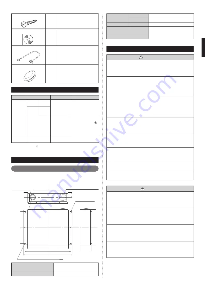
Dimensions
41 11
The Network Convertor is comprised of a body and cover.
211 (8-5
/16)
241.6 (9-1/2)
288 (11-11/32)
2-Ø5 (3/16)
67
(2-5/8)
89.5
(3-17/32)
89.5
(3-17/32)
29
(1
-5
/3
2)
Ø28 (1-3/32)
For dust proof
bushing
4 - Ø5 (3/16) For M4x20mm screws
Ø28 (1-3/32)
For dust proof bushing
For M4x20mm
screws
272 (10-23/32) Hole pitch
95 (
3-
3/
4)
H
ol
e p
itc
h
95 (
3-
3/
4)
H
ol
e p
itc
h
Unit : mm (in.)
Ø22.2 (7/8) For conduit
Power supply
1Ø AC208–240V
50/60 Hz
Power consumption (W)
4.5


