En-22
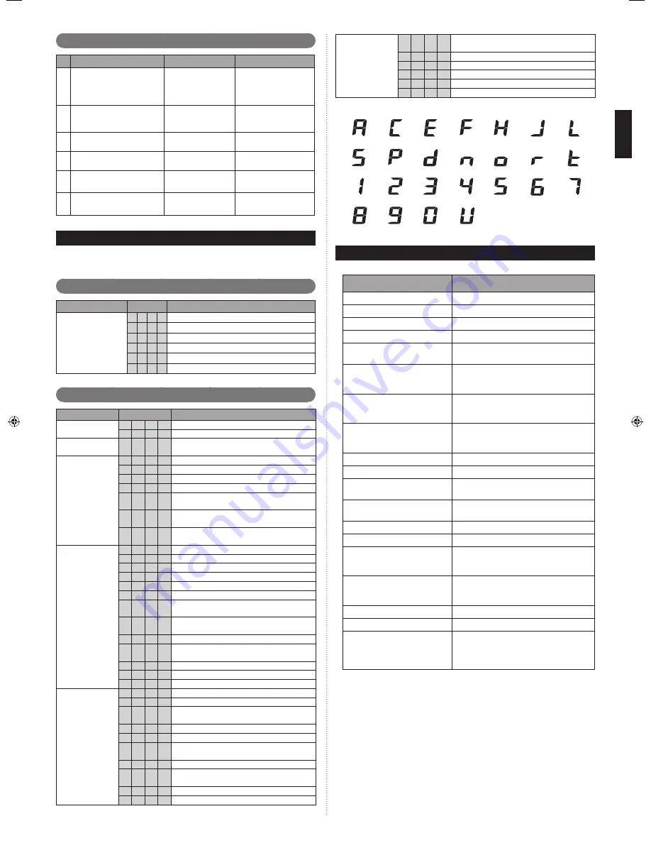
Checklist
9. 4.
Check description
Check method
Criteria
1
High and low pressure values
are normal.
Check it with a pres-
sure gauge.
Cooling: low pressure
approx. 0.8 MPa
Heating: high pressure
approx. 3.0 MPa
2
Drain water is discharged
smoothly through the drain
hose.
Check it by pouring
water.
―
3
Indoor and outdoor unit fans
are operating.
Check them visually.
―
4
Compressor operates after
the indoor unit operates.
Check the operating
sound.
―
5
Difference between inlet and
outlet temperatures is normal.
Measure the inlet and
outlet temperatures.
Temperature difference
10 degrees
6
Error is not displayed
Check the 7 segment
display
Error blinking or no error
code display
LED Display
10.
You can determine the operating status by the lighting up and blinking of the LED dis-
play.
Check the status using the table below.
Normal operation mode
10. 1.
Mode
CODE
DESCRIPTION
Operation
C L
Cooling
H
t
Heating
o
r During oil recovery operation
d F During defrosting operation
P C During power saving operation
L n During low noise operation
Error display mode
10. 2.
Mode
CODE
DESCRIPTION
Communication
error
E
1
4.
2
Outdoor unit network communication 2 error
E
1
4.
5
The number of indoor unit shortage
Indoor unit
actuator error
E
5
U.
1
Indoor unit miscellaneous error
Outdoor unit
PCB/Electrical
component/
Switch error
E
6
2.
3
Outdoor unit EEPROM access error
E
6
2.
6
Outdoor unit inverters communication error
E
6
2.
8
Outdoor unit EEPROM data corruption error
E
6
3.
1
Outdoor unit inverter error
E
6
7.
2
Outdoor unit inverter PCB power short interrup-
tion error
E
6
8.
2
Outdoor unit rush current limiting resister temp.
rise error (protective operation)
E
6
9.
1
Outdoor unit transmission PCB parallel com-
munication error
Outdoor unit
sensor error
E
7
1.
1
Outdoor unit discharge temp. thermistor 1 error
E
7
2.
1
Outdoor unit compressor temp. thermistor 1 error
E
7
3.
3
Outdoor unit heat ex. liquid temp. thermistor error
E
7
4.
1
Outside air temp. thermistor error
E
7
5.
1
Outdoor unit suction gas temp. thermistor error
E
7
7.
1
Outdoor unit heat sink temp. thermistor error
E
8
2.
1
Outdoor unit sub-cool heat ex. gas inlet temp.
thermistor error
E
8
2.
2
Outdoor unit sub-cool heat ex. gas outlet temp.
thermistor error
E
8
3.
2
Outdoor unit liquid pipe temp. thermistor 2 error
E
8
4.
1
Outdoor unit current sensor 1 error
(permanent stop)
E
8
6.
1
Outdoor unit discharge pressure sensor error
E
8
6.
3
Outdoor unit suction pressure sensor error
E
8
6.
4
Outdoor unit high pressure switch 1 error
Outdoor unit
actuator error
E
9
3.
1
Outdoor unit inverter compressor start up error
E
9
4.
1
Outdoor unit trip detection
E
9
5.
5
Outdoor unit compressor motor loss of synchro-
nization
E
9
7.
1
Outdoor unit fan motor 1 lock error
E
9
7.
4
Outdoor unit fan motor 1 undervoltage
E
9
7.
5
Outdoor unit fan motor 1 temperature error
(protective action)
E
9
8.
1
Outdoor unit fan motor 2 lock error
E
9
8.
5
Outdoor unit fan motor 2 temperature error
(protective action)
E
9
A.
1
Outdoor unit coil 1 (expansion valve 1) error
E
9
A.
2
Outdoor unit coil 2 (expansion valve 2) error
Refrigerant
system error
E
A
1.
1
Outdoor unit discharge temperature 1 error
(permanent stop)
E
A
3.
1
Outdoor unit compressor 1 temperature error
E
A
4.
1
Outdoor unit high pressure error
E
A
4.
2
Outdoor unit high pressure protective action 1
E
A
5.
1
Outdoor unit low pressure error
E
A
C.
4
Outdoor unit heat sink temperature error
㪣
㪣㪜㪛㩷㫃㪸㫄㫇㩷㪑
㪃
㪃
㪃
㪃
㪃
㪃
㪃
㪃
㪣㪑
㪟㪑
㪡㪑
㪃
㪍㪑
㪃
㪃
㪃
㫅㪑
㫆㪑
㫉㪑
㫋㪑
㪃
㪃
㪃
㪃
㪬㪑
㪃
㪐㪑
㪏㪑
㪃
㪃
㪃
㪃
㪧㪑
㪻㪑
㪪㪑
㪘㪑
㪝㪑
㪚㪑
㪜㪑
㪇㪑
㪌㪑
㪃
㪃
㪃
㪃
㪃
㪊㪑
㪈㪑
㪉㪑
㪃
㪎㪑
㪋㪑
INFORMATION
11.
Main contents of label
Item
Detail
Model name
1.
Model name
Serial number
2.
Serial number
Electric characteristics
3.
Phase, rated voltage, and frequency
Weight
4.
Product weight
Capacity
5.
Cooling/heating capacity under cooling/
heating condition (refer to item 15)
Current
6.
Electric current during cooling/heating
operation under cooling/heating condition
(refer to item 15)
Input power
7.
Input during cooling/heating operation
under cooling/heating condition (refer to
item 15)
Max. Current
8.
Maximum electric current (temperature
condition is max. cooling condition [refer
to item 16])
Air circulation
9.
Air circulation
Noise level
10. Noise
level
Refrigerant
11.
Refrigerant type and initial charging
amount
Max. pressure (HP/LP)
12.
Means pressure of High Pressure side/
Low Pressure side
Protection
13.
Protection level against dust and water
Working temperature
14. Working
temperature
Condition of cooling/heating
15.
Dry-bulb temperature and wet-bulb tem-
perature under standard cooling/heating
condition
Condition of max. cooling
16.
Dry-bulb temperature and wet-bulb tem-
perature at maximum electric current and
input
Manufacture year
17. Manufacture
year
Origin
18. Origin
country
Manufacturer
19.
Manufacturer
FUJITSU GENERAL LIMITED
Address: 1116, Suenaga, Takatsu-ku,
Kawasaki 213-8502, Japan
9380545026-02_IM.indb 22
9380545026-02_IM.indb 22
19/08/2013 17:20:12
19/08/2013 17:20:12


