En-4
CAUTION
Installation methods not shown in the following examples are not recommended.
Performance may drop signi
fi
cantly.
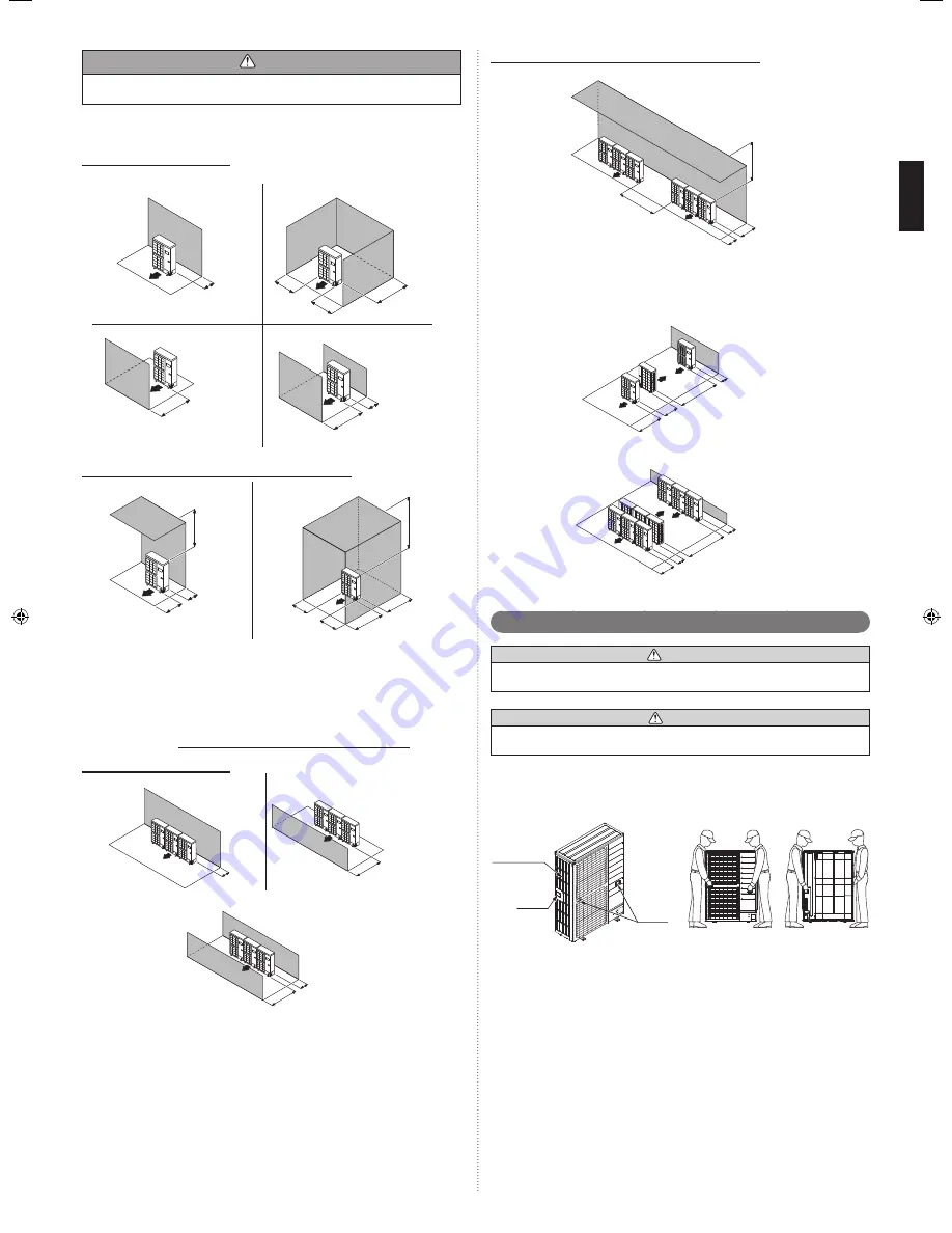
3.3.1. Single outdoor unit installation
When the upward area is open
(Unit: mm)
(1) Obstacles at rear only
150
(2) Obstacles at rear and sides only
200
300
200
(3) Obstacles at front only
1000 or more
(4) Obstacles at front and rear only
1000 or more
150
When an obstruction is present also in the upward area
(Unit: mm)
(1) Obstacles at rear and above only
300
Max. 500
1000
(2) Obstacles at rear, sides, and above only
1500
250
250
500
Max. 500
3.3.2. Multiple outdoor unit installation
Provide at least 25 mm of space between the outdoor units if multiple units are
•
installed.
When routing the piping from the side of an outdoor unit, provide space for the piping.
•
No more than 3 units must be installed side by side.
•
When 3 units or more are arranged in a line, provide the space as shown in the
following example when an obstruction is present also in the upward area.
When the upward area is open
(Unit: mm)
(1) Obstacles at rear only
300
(2) Obstacles at front only
1500 or more
(3) Obstacles at front and rear only
500
1500 or more
When an obstruction is present also in the upward area
(Unit: mm)
Obstacles at rear and above only
•
1500
500
Max. 300
1500
3.3.3. Outdoor units installation in multi row
(Unit: mm)
The following settings are not recommended in case of cooling by a low outside tem-
*
perature.
(1) Single parallel unit arrangement
150
600
1000
2000 or more
(2) Multiple parallel unit arrangement
500
600
1500
3000 or more
Transporting the unit
3. 4.
WARNING
Do not touch the
fi
ns.
Otherwise, personal injury could result.
CAUTION
When carrying the unit, hold the handles on the right and left sides and be careful.
If the outdoor unit is carried from the bottom, hands or
fi
ngers may be pinched.
Carry slowly in the manner as shown on “Fig. B” holding the handles “Fig. A” in right
•
and left sides. (Be careful not to touch with hands or objects.)
Be sure to hold the handles on the sides of the unit. Otherwise, the suction grilles on
•
the sides of the unit may be deformed.
Front view
Rear view
Fig. B
Handle
Handle
Suction grille
Fig. A
9380545026-02_IM.indb 4
9380545026-02_IM.indb 4
19/08/2013 17:19:18
19/08/2013 17:19:18


