16
Brocade 6545 Gen5 16-Gbps FC Switch Module Hardware Reference Guide
53-1003184-01
Inserting the Switch Module in the blade server
2
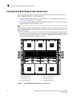
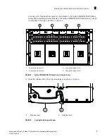
4. Pull the release lever out completely so the Switch Module can be seated properly in the
Fujitsu PRIMERGY BX900 S2 or BX400 Blade Server I/O module bay.
5. With the port side facing you and the release lever fully extended, slide the Switch Module into
the appropriate Fujitsu PRIMERGY BX900 S2 or BX400 Blade Server I/O module bay.
6. Push the release lever inward until the release latch clicks into place.
This locks the Switch Module in the Fujitsu PRIMERGY BX900 S2 or BX400 Blade Server I/O
module bay. Locking the Switch Module in the I/O module bay provides power (if the power is
on in the Fujitsu PRIMERGY BX900 S2 or BX400 Blade Server) and activates (powers on) the
Switch Module and the LEDs.
The Switch Module then runs self-diagnostic tests, such as POST.
After the Switch Module is inserted in the Fujitsu PRIMERGY BX900 S2 or BX400 Blade Server,
the physical Ethernet connection is established through the Fujitsu PRIMERGY BX900 S2 or
BX400 Blade Server Management Blade (MMB).
NOTE
Once inserted, the Switch Module can be accessed remotely. Ensure that the Switch Module is
not being modified from any other connection until configuration is complete. Refer to
Chapter
3, “Configuring the Brocade 6545 16 Gbps FC Switch Module,”
for information about
configuration.
You are now ready to insert the SFP+ optical transceivers. For more information, refer to
“Inserting
SFP+ optical transceivers and cables”
on page 19.
NOTE
Be sure to use only Brocade-branded SFP+ optical transceivers. Unapproved products will not be
recognized.
It is recommended that you review the guidelines when handling SFP+ optical transceivers and
cables before you insert the transceivers and attach the cables. Refer to
“Installation and safety
considerations when handling transceivers and cables”
on page 17 for more information.


