38
Brocade 6545 Gen5 16-Gbps FC Switch Module Hardware Reference Manual
53-1003184-01
Diagnostic tests
4
Diagnostic tests
In addition to Power-on Self Test (POST), the Fabric OS includes diagnostic tests to help
troubleshoot the hardware and the firmware, including tests of internal connections and circuitry,
fixed media, and the transceivers and cables in use.
Initiate diagnostic tests with the command line using a Telnet session or a terminal set up with a
serial connection to the switch. Some tests require the ports to be connected by external cables to
allow diagnostics to verify the serializer/deserializer interface, transceiver, and cable. For
information on available diagnostic tests, use the diagHelp command.
All diagnostic tests are run at link speeds of 16 Gbps.
NOTE
Diagnostic tests can temporarily lock the transmit and receive speed of the links during diagnostic
testing.
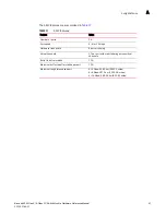
Table 4
lists external LED activity during diagnostic testing.
NOTE
Diagnostic tests can temporarily lock the transmit and receive speed of the links during testing.
Interpreting LED activity
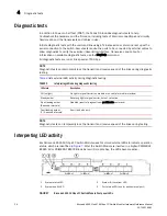
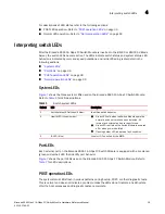
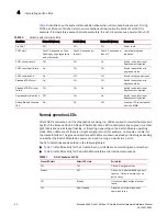
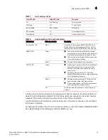
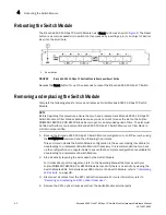
Each Brocade 6545 16 Gbps FC Switch Module uses bi-colored external LEDs to indicate operation
status, which are identified in
Figure 7
. After the Switch Module is inserted in a Fujitsu PRIMERGY
BX900 S2 or PRIMERGY BX400 Blade Server I/O module bay, the LEDs become active.
FIGURE 7
Brocade 6545 16 Gbps FC Switch Module front panel LEDs
TABLE 4
Interpreting LEDs during diagnostic testing
LED state
Description
Off (no light)
No light or signal carrier (no module or no cable for media interface)
Steady amber
Receiving light or signal carrier, but not yet online
Slow flashing amber
(2-second intervals)
Disabled (result of diagnostics or portDisable command)
Fast flashing amber
(1/2- second intervals)
Error (fault with port)
1
System status LED
3
System ID (Location) LED
2
System health LED
4
Port status LED (one for each external port)

