Brocade 6545 Gen5 16-Gbps FC Switch Module Hardware Reference Manual
43
53-1003184-01
Removing and replacing the Switch Module
4
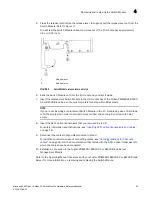
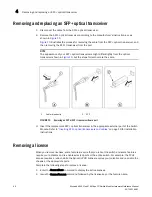
5. Press the release latch to free the release lever, then gently pull the release lever out from the
Switch Module. Refer to
Figure 9
.
You will feel the Switch Module unseat and move out of the I/O module bay approximately
0.6 cm (0.25 inch).
FIGURE 9
Switch Module release lever and latch
6. Slide the Switch Module out from the I/O module bay and set it aside.
7. Insert the replacement Switch Module in the I/O module bay of the Fujitsu PRIMERGY BX900
S2 or BX400 Blade Server. You must complete this step within 60 seconds.
NOTE
If you are not inserting a replacement Switch Module in the I/O module bay, use a filler blade
to fill the empty slot in order to maintain proper airflow and cooling. Do not leave the slot
empty.
8. Insert the SFP+ optical transceivers that you removed in step 4.
For safety information and instructions, see
“Inserting SFP+ optical transceivers and cables”
on page 19.
9. Reconnect the cables that you disconnected in step 3.
For additional information about connecting cables, see
“Cabling guidelines for fiber-optic
cables”
on page 18, and the documentation that comes with the SFP+ optical transceivers to
which the cables have been connected.
10. Establish a connection to the Fujitsu PRIMERGY BX900 S2 or BX400 Blade Server
Management Module.
Refer to the Operating Manual
that comes with your Fujitsu PRIMERGY BX900 S2 or BX400 Blade
Server for more information on removing and replacing the Switch Module.
1
Release lever
2
Release latch


