background image

FNC00164

5_R

ev_01

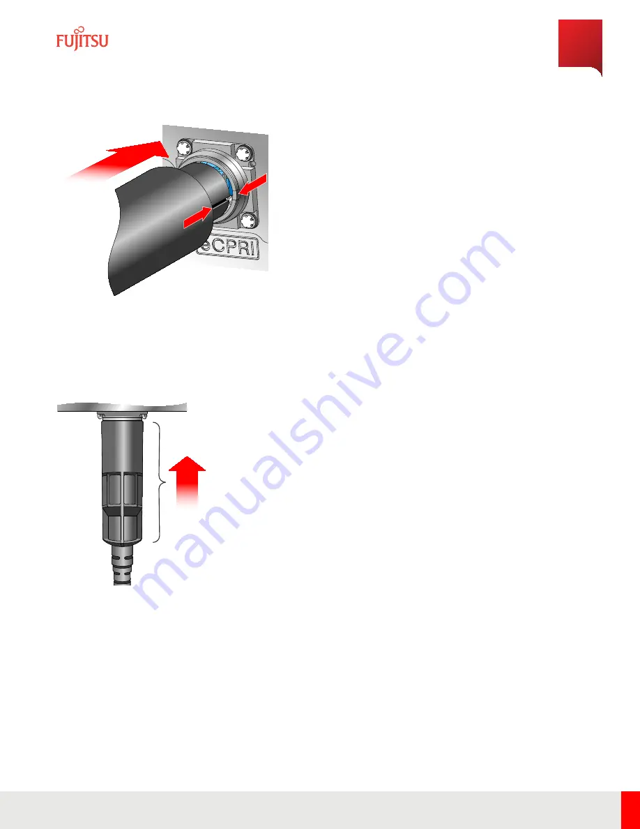
Figure 36

Align Connector

Step 11

Insert the cable and turn the enclosure sub-assembly clockwise until it clicks into place.

FNC00163

8_R

ev_01

Figure 37

Insert Connector

Installation

Cable Installation

119

Release 1.0

 · 

Issue 1.1, May 2021

Fujitsu and Fujitsu Customer Use Only

Summary of Contents for CFD5GRUDB3

Page 1: ...atherproofing method to prevent moisture intrusion 13 mm socket Philips screwdriver Danger Use properly insulated tools and perform all safety precautions in accordance with local safety practices when working on or around power terminals power cables and power connectors Contacting power terminals uninsulated conductors cable wiring or any connector that could be part of a live electrical circuit...

Page 2: ...ue de choc électrique Pour une installation aux États Unis reportez vous aux articles 810 840 du National Electrical Code ANSI NFPA No 70 pour obtenir des informations sur la mise à la terre appropriée et la protection contre la foudre applicable pour les équipements de télécommunications et le câblage L installateur doit également suivre toute réglementation locale supplémentaire du code du bâtim...

Page 3: ... power terminals uninsulated conductors cable wiring or any connector that could be part of a live electrical circuit can result in death or serious personal injury Danger Utilisez des outils correctement isolés et appliquez toutes les précautions de sécurité conformément à la sécurité locale pratiques lorsque vous travaillez sur ou autour des bornes d alimentation des câbles d alimentation et des...

Page 4: ...re 29 eCPRI Port Location FNC001634_Rev_01 Figure 30 Remove Protective Cap Step 2 Install the SFP into the eCPRI port Installation Cable Installation 115 Release 1 0 Issue 1 1 May 2021 Fujitsu and Fujitsu Customer Use Only ...

Page 5: ...SFP into the port until the lever closes fully FNC001636_Rev_01 Figure 32 SFP Module Inserted Step 4 Remove the protective covers from both mating connectors Installation Cable Installation 116 Release 1 0 Issue 1 1 May 2021 Fujitsu and Fujitsu Customer Use Only ...

Page 6: ... FNC001643_Rev_01 Figure 34 Remove Cap from Optical Cable Step 6 Pull back on the fiber enclosure until the cylindrical cable container is completely visible Step 7 Clean the optical fiber connections Installation Cable Installation 117 Release 1 0 Issue 1 1 May 2021 Fujitsu and Fujitsu Customer Use Only ...

Page 7: ... pre positioned in the connector of the RU FNC001640_Rev_01 Figure 35 Insert Optical Fiber Step 9 Ensure the locking latches of the LC fiber connectors are snapped into position Step 10 Align the connector key on connector to the connector on the RU and insert the connector Installation Cable Installation 118 Release 1 0 Issue 1 1 May 2021 Fujitsu and Fujitsu Customer Use Only ...

Page 8: ...tep 11 Insert the cable and turn the enclosure sub assembly clockwise until it clicks into place FNC001638_Rev_01 Figure 37 Insert Connector Installation Cable Installation 119 Release 1 0 Issue 1 1 May 2021 Fujitsu and Fujitsu Customer Use Only ...

Page 9: ...ay use any UL approved weatherproofing material Refer to Weatherproofing RU Connections for more information about weatherproofing methods Continue with the next task 4 6 3 Connect AISG Cables This procedure describes how to connect AISG cables to the RU Prerequisites RU mounted and not powered up Available AISG cables Weatherproofing method to prevent moisture intrusion Step 1 Remove the protecti...

Page 10: ...cable Step 6 Apply weatherproofing to the AISG cable connector per local guidelines to prevent moisture intrusion Note Fujitsu recommends using industry standard UL approved self fusing tape but users may use any UL approved weatherproofing material Refer to Weatherproofing RU Connections for more information about weatherproofing methods Continue with the next task 4 6 4 Connect RF Cables This pr...

Page 11: ...ommager RU Le niveau d entrée absolu maximal du port Rx est de 3 5 dBm 5 minutes maximum sur la base des spécifications de blocage dans la bande 3GPP Step 1 Remove the protective covers from the RF ports on the bottom of the RU FNC001720_Rev_01 Figure 40 RF Port Locations Step 2 If necessary insert two weatherproofing sleeves onto each cable Step 3 Connect each RF cable to its corresponding port o...

Page 12: ...weatherproofing methods Continue with the next task 4 6 5 Connect DC 48 V Power Cable This procedure describes how to connect DC 48 V power cable Prerequisites Torx driver RU mounted and not powered up Available 48V power cable Important If the power cable connector on the RU is connected in reverse the RU does not start and is not damaged because of the anti reverse circuit Step 1 Remove the dust...

Page 13: ... Cover Step 2 Align the key in the plug with the inner and outer connector grooves FNC001654_Rev_01 Figure 42 Align Key Plug with Port Installation Cable Installation 124 Release 1 0 Issue 1 1 May 2021 Fujitsu and Fujitsu Customer Use Only ...

Page 14: ...on in case the DC power leads are connected incorrectly Step 4 Turn the locking ring clockwise until tightened FNC001656_Rev_01 Figure 43 Tighten Power Cable This task is complete Installation Cable Installation 125 Release 1 0 Issue 1 1 May 2021 Fujitsu and Fujitsu Customer Use Only ...

Page 15: ... in band blocking specifications Avertissement Évitez une alimentation électrique excessive pour éviter d endommager RU Le niveau d entrée absolu maximal du port Rx est de 3 5 dBm 5 minutes maximum sur la base des spécifications de blocage dans la bande 3GPP Important The RU does not have a power switch DC power on off is controlled by the circuit breaker of the DC power source The circuit breaker...

Page 16: ...nput optical signals higher than the maximum light level as this may damage the optical receiver Do not submerge or bury in snow Power Up 127 Release 1 0 Issue 1 1 May 2021 Fujitsu and Fujitsu Customer Use Only ...

Page 17: ...he circuit breaker until it s time to power up the RU Note It takes less than one minute for the RU to fully power up Step 3 Verify weatherproofing is applied to each cable connector according to local guidelines Note Fujitsu recommends using industry standard UL approved self fusing tape but users may use any UL approved weatherproofing material Refer to Weatherproofing RU Connections for more in...

Page 18: ...t the circuit breaker to ON at the DC power supply Note Reset starts when RU detects power on Step 2 Wait approximately one minute for the RU to fully power up Continue with the next task Power Up Apply Power to RU 129 Release 1 0 Issue 1 1 May 2021 Fujitsu and Fujitsu Customer Use Only ...

Page 19: ...ned back on to allow the RU to initialize Attention Si l alimentation du RU est coupée une attente minimale de 10 secondes est nécessaire avant de la mettre sous tension de nouveau pour permettre à l EUR de s initialiser Note If the fault LED is on check the connections at the RU and power source and optical connection sources to resolve the issue Note If the LED is not blinking green after reset ...

Page 20: ... The following table shows the status of the LEDs Table 37 RU LED Status RU Status LED Operation Fault Fronthaul Operational Green blinking Red off n a Transmit ON Green on Red off n a Blocking Green blinking Red blinking n a Major Alarm Green off Red blinking n a Minor Alarm Green blinking or Green on Red blinking n a Power Up LED Display 131 Release 1 0 Issue 1 1 May 2021 Fujitsu and Fujitsu Cus...

Page 21: ... Operation Fault Fronthaul L1 disconnection n a n a n a L1 link found M Plane not found n a n a Green blinking L1 M Plane link found n a n a Green on Power Up LED Display 132 Release 1 0 Issue 1 1 May 2021 Fujitsu and Fujitsu Customer Use Only ...

Page 22: ...erify if any active alarms are present Note If any alarms or conditions exist create trouble tickets as needed to address them Step 2 Confirm with the customer that the work is completed successfully Step 3 Clean up area before leaving the customer premises This task is complete Power Up Verify Alarm Status 133 Release 1 0 Issue 1 1 May 2021 Fujitsu and Fujitsu Customer Use Only ...

Page 23: ...iving configuration information from the DU during the confirmation The method and procedure of the confirmation are presented by the DU vendor Power Up RU Confirmation 134 Release 1 0 Issue 1 1 May 2021 Fujitsu and Fujitsu Customer Use Only ...

Page 24: ...nd Trouble Clearing In this chapter 6 1 RU Alarms 6 2 Replace RU Mounted on Pole 6 3 Replace RU Mounted on Wall Maintenance and Trouble Clearing 135 Release 1 0 Issue 1 1 May 2021 Fujitsu and Fujitsu Customer Use Only ...

Page 25: ...Action Software on RU is operating abnormally Critical Reset Table 40 Initialization failure Probable Cause Severity Corrective Action Software on RU is operating abnormally Note Stops all RF transmission Critical Reset Table 41 Fronthaul Port Status Change Probable Cause Severity Corrective Action SFP not implemented SFP LOS SFP TxFault SFP 12C Access NG L1 OFF M Plane OFF Note Stops all RF trans...

Page 26: ...re out of range condition low temp Probable Cause Severity Corrective Action Temperature is too low Major Adjust node temperature to within the RU threshold operating temperature Table 45 TX Power status change Probable Cause Severity Corrective Action TxGainALM Port A D Note Stops RF transmission at port with alarm Major Reset Table 46 Cold start Probable Cause Severity Corrective Action RU too c...

Page 27: ...on Table 49 IQ over Input Probable Cause Severity Corrective Action IQ over Input ALM Note Stops RF transmission at port with alarm Major Reset Table 50 VSWR alarm Probable Cause Severity Corrective Action VSWR ALM Note Stops RF transmission at port with alarm Major Reset Table 51 RX out of order Probable Cause Severity Corrective Action RxGainALM Note Stops RF transmission at port with alarm Majo...

Page 28: ...hange Probable Cause Severity Corrective Action Channel frequency has changed Note Reports alarm only Minor Take no action Table 55 RU Parameter change Probable Cause Severity Corrective Action RU parameter has changed Note Reports alarm only Minor Take no action Table 56 RU Local Access Attempt Probable Cause Severity Corrective Action A local access attempt has been made on the RU Minor Take no ...

Page 29: ...ivent être déconnectés de l EF avant de commencer cette procédure Caution The RU is heavy Fujitsu recommends removing the RU on a two person team to avoid damage to the unit or injury to the user Attention Le RU est lourd Fujitsu recommande de retirer l EF d une équipe de deux personnes pour éviter d endommager l appareil ou des blessures à l utilisateur Step 1 If necessary attach hoisting equipme...

Page 30: ...lts from the top of the mounting plate Step 4 Cautiously lift the RU from the mounting plate and lower to the ground using the eye bolts per local guidelines Maintenance and Trouble Clearing Replace RU Mounted on Pole 141 Release 1 0 Issue 1 1 May 2021 Fujitsu and Fujitsu Customer Use Only ...

Page 31: ...t the replacement RU to the pole by aligning the hooks on the plate adapter with the two holes at the top of the wall mounting plate Maintenance and Trouble Clearing Replace RU Mounted on Pole 142 Release 1 0 Issue 1 1 May 2021 Fujitsu and Fujitsu Customer Use Only ...

Page 32: ...apter plate to the mounting plate using M10 x 30 mm bolts and split and flat washers Do not tighten the bolts yet Step 7 Torque each bolt on the top and bottom of the mounting plate using a 11 16 socket to 27 Nm This task is complete Maintenance and Trouble Clearing Replace RU Mounted on Pole 143 Release 1 0 Issue 1 1 May 2021 Fujitsu and Fujitsu Customer Use Only ...

Page 33: ... procédure Caution The RU is heavy Fujitsu recommends installing the RU with a two person team to avoid damage to the unit or injury to the user Attention Le RU est lourd Fujitsu recommande de retirer l EF d une équipe de deux personnes pour éviter d endommager l appareil ou des blessures à l utilisateur Step 1 If necessary attach hoisting equipment to eye bolts on top of the RU Step 2 Remove the ...

Page 34: ...r FNC001582_Rev_02 Figure 48 Remove M10 Bolts Step 4 Unhook the RU from the Wall Mount Plate and place it somewhere safe Note Use the eye bolts to hoist the RU Maintenance and Trouble Clearing Replace RU Mounted on Wall 145 Release 1 0 Issue 1 1 May 2021 Fujitsu and Fujitsu Customer Use Only ...

Page 35: ...5_Rev_02 Figure 49 Removing Radio from Wall Mount Step 5 Mount the replacement RU by aligning the holes on the Wall Mount Plate Adapter with the holes on the top of the Wall Mount Plate and hook it in place Maintenance and Trouble Clearing Replace RU Mounted on Wall 146 Release 1 0 Issue 1 1 May 2021 Fujitsu and Fujitsu Customer Use Only ...

Page 36: ... x 30 bolts into the holes on the top of the RU with flat and split washers used for spacing b Loosely screw two M10 x 40 bolts into the holes on the lower front of the RU with an insulating stepped bushing and flat and split washers used for spacing Ensure the shoulder of the stepped bushing is perfectly fit inside of the hole on the L bracket for proper alignment Maintenance and Trouble Clearing...

Page 37: ...shing Flat Washer FNC001582_Rev_02 Figure 51 Securing RU to Wall Mount Plate Step 7 Torque all four M10 bolts to 27 Nm to secure the RU in place Maintenance and Trouble Clearing Replace RU Mounted on Wall 148 Release 1 0 Issue 1 1 May 2021 Fujitsu and Fujitsu Customer Use Only ...

Page 38: ...C001651_Rev_01 Figure 52 Wall Mount Final Result This task is complete Maintenance and Trouble Clearing Replace RU Mounted on Wall 149 Release 1 0 Issue 1 1 May 2021 Fujitsu and Fujitsu Customer Use Only ...

Page 39: ...jury to the user Attention Manipulez le RU avec précaution car il est lourd Fujitsu recommande d installer le RU surdeuxéquipe de personnes pour éviter d endommager l unité ou de blesser l utilisateur Caution If the RU is being removed from a high location Fujitsu recommends using lifting equipment to hoist the RU by a pair of eye bolts mounted on the RU Attention Si l EF est retirée d un emplacem...

Page 40: ... could be part of a live electrical circuit can result in death or serious personal injury Danger Utilisez des outils correctement isolés et appliquez toutes les précautions de sécurité conformément à la sécurité locale pratiques lorsque vous travaillez sur ou autour des bornes d alimentation des câbles d alimentation et des connecteurs d alimentation Contacter bornes d alimentation conducteurs no...

Page 41: ...ep 1 Remove the weatherproofing from each connector according to local guidelines Step 2 Loosen each RF connection between the RU and the antenna Step 3 Disconnect the RF cables from the RF port on the RU Step 4 Insert protective covers into the RF ports Continue with the next task 7 1 3 Remove AISG Cable This procedure describes how to remove AISG RET cable from the RU Prerequisite RU powered off...

Page 42: ...ble from the antenna side Step 4 Insert a protective cover on the AISG port This task is complete 7 1 4 Remove Optical Cable This procedure describes how to remove optical cable from the RU Prerequisite RU powered off Danger Use properly insulated tools and perform all safety precautions in accordance with local safety practices when working on or around power terminals power cables and power conn...

Page 43: ... or any connector that could be part of a live electrical circuit can result in death or serious personal injury Danger Utilisez des outils correctement isolés et appliquez toutes les précautions de sécurité conformément à la sécurité locale pratiques lorsque vous travaillez sur ou autour des bornes d alimentation des câbles d alimentation et des connecteurs d alimentation Contacter bornes d alime...

Page 44: ...power terminals uninsulated conductors cable wiring or any connector that could be part of a live electrical circuit can result in death or serious personal injury Danger Utilisez des outils correctement isolés et appliquez toutes les précautions de sécurité conformément à la sécurité locale pratiques lorsque vous travaillez sur ou autour des bornes d alimentation des câbles d alimentation et des ...

Page 45: ...d Step 2 Unscrew the RU end of the FG cable and remove Step 3 Using a screwdriver or 13 mm socket detach screws from the ground point This task is complete Removal Cable Removal 156 Release 1 0 Issue 1 1 May 2021 Fujitsu and Fujitsu Customer Use Only ...

Page 46: ...blage doivent être déconnectés de l EF avant de commencer cette procédure Caution The RU is heavy Fujitsu recommends removing the RU on a two person team to avoid damage to the unit or injury to the user Attention Le RU est lourd Fujitsu recommande de retirer l EF d une équipe de deux personnes pour éviter d endommager l appareil ou des blessures à l utilisateur Step 1 If necessary attach hoisting...

Page 47: ...e M10 x 30 mm bolts from the top of the mounting plate Step 4 Cautiously lift the RU from the mounting plate and lower to the ground using the eye bolts per local guidelines Removal Detach RU From Pole 158 Release 1 0 Issue 1 1 May 2021 Fujitsu and Fujitsu Customer Use Only ...

Page 48: ...bers together Step 6 Disconnect the small crossmembers from the large crossmembers by removing the 10 inch 3 8 bolts Note Fujitsu recommends removing the pole mount plate on a 2 person team to prevent injury or damage to the equipment This task is complete Removal Detach RU From Pole 159 Release 1 0 Issue 1 1 May 2021 Fujitsu and Fujitsu Customer Use Only ...

Page 49: ... l EF avant de commencer cette procédure Caution The RU is heavy Fujitsu recommends removing the RU on a two person team to avoid damage to the unit or injury to the user Attention Le RU est lourd Fujitsu recommande de retirer l EF d une équipe de deux personnes pour éviter d endommager l appareil ou des blessures à l utilisateur Note Attach a hoist to the eye bolts to support the RU during remova...

Page 50: ...shing Flat Washer FNC001582_Rev_02 Figure 56 Remove M10 Bolts Step 3 Unhook the RU from the Wall Mount Plate and place it somewhere safe Note Use the eye bolts to hoist the RU Removal Detach RU from Wall 161 Release 1 0 Issue 1 1 May 2021 Fujitsu and Fujitsu Customer Use Only ...

Page 51: ...Washer Split Washer Flat Washer FNC001605_Rev_02 Figure 57 Removing Radio from Wall Mount Step 4 Remove the RU Wall Mount Plate from the wall by unscrewing all four nuts on the M10 bolts in the wall Removal Detach RU from Wall 162 Release 1 0 Issue 1 1 May 2021 Fujitsu and Fujitsu Customer Use Only ...

Page 52: ...1_Rev_02 Figure 58 Removing Wall Mount Plate from Wall Step 5 Remove the Wall Mount Plate and the M10 bolts from the wall This task is complete Removal Detach RU from Wall 163 Release 1 0 Issue 1 1 May 2021 Fujitsu and Fujitsu Customer Use Only ...

Page 53: ... wrench Power tools optional Metric and SAE toolkit Step 1 Unscrew the two M10 x 30 bolts from the front of the mounting adapter plate FNC001601_Rev_03 Figure 59 Removing Bolts from Mounting Adapter Plate Step 2 Remove the flat and split washers insulating bushings and mounting plate from the RU Removal Detach RU Mounting Adapter Plate 164 Release 1 0 Issue 1 1 May 2021 Fujitsu and Fujitsu Custome...

Page 54: ...FNC001625_Rev_01 Figure 60 Removing Mounting Adapter Plate Continue with the next task Removal Detach RU Mounting Adapter Plate 165 Release 1 0 Issue 1 1 May 2021 Fujitsu and Fujitsu Customer Use Only ...

Page 55: ...s optional Metric and SAE toolkit Step 1 Unscrew the two M8 eye bolts from the two holes on top of the RU and collect the washers Step 2 Unscrew the eight M8 screws on the L brackets on each side of the RU Step 3 Remove the L brackets from each side of the RU Removal Remove L Brackets and Eye Bolts 166 Release 1 0 Issue 1 1 May 2021 Fujitsu and Fujitsu Customer Use Only ...

Page 56: ...lat Washer Flat Washer NOTE Use torque value of 9 28 N m FNC001596_Rev_01 Figure 61 Removing L Brackets and Eye Bolts This task is complete Removal Remove L Brackets and Eye Bolts 167 Release 1 0 Issue 1 1 May 2021 Fujitsu and Fujitsu Customer Use Only ...

Page 57: ...pecification of ORAN version ORAN WG4 MP 0 v02 00 ORAN WG4 IOT 0 v01 00 Telecom Slave Clock T TSC to G8275 1 and Assisted Partial Timing Support IEEE 1588 IEEE 1914 1 ITU T G 826x SyncE G 827x series GR 63 NEBS Requirements Physical Protection GR 487 Salt fog IEC UL62368 1 2nd edition Product safety UL 50E UL60950 22 CSA C22 2 Outdoor specification 3GPP 38 113 NR Base Station BS Electromagnetic Co...

Page 58: ...tion and Radio Treaty Matters CFR 47 Part 2 Unintentional radiation CFR 47 Part 15 Misc Communication Services CFR 47 Part 27 Private Land Mobile Radio Services CFR 47 Part 90 FCC rules on output power as outlined in part 90 90 617 90 691 and part 27 27 53 3GPP TS 25 461 NR Iuant interface Layer1 v6 5 0 2005 12 References 169 Release 1 0 Issue 1 1 May 2021 Fujitsu and Fujitsu Customer Use Only ...

Page 59: ...te configuration of a device with little to no pre defined information in the Radio Unit RU The following figures outline the ZTP sequence Figure 62 Acquiring IP Address ZTP Overview 170 Release 1 0 Issue 1 1 May 2021 Fujitsu and Fujitsu Customer Use Only ...

Page 60: ...Figure 63 Configuration Files are Requested and Sent ZTP Overview 171 Release 1 0 Issue 1 1 May 2021 Fujitsu and Fujitsu Customer Use Only ...

Page 61: ...Figure 64 Configuration Files Loaded and RU Becomes Operational ZTP Overview 172 Release 1 0 Issue 1 1 May 2021 Fujitsu and Fujitsu Customer Use Only ...

Page 62: ...and remove Danger Ne manipulez jamais la fibre exposée à mains nues et ne la touchez jamais à la peau de base Des fragments de fibre peuvent entrer la peau et sont difficiles à détecter et à éliminer Caution Clean the optical connector before inserting and after removal Attention Nettoyez le connecteur optique avant de l insérer et après son retrait The RU has one optical interface used for the eC...

Page 63: ...Figure 66 Reel type Cleaner Tool Opened Figure 67 Stick Cleaner Tool Optical Connector Cleaning 174 Release 1 0 Issue 1 1 May 2021 Fujitsu and Fujitsu Customer Use Only ...

Page 64: ... the cleaner a second time If more cleaning is needed use a different area on the cleaner or a new cleaner Caution Do not rotate the connector while cleaning Attention Ne faites pas tourner le connecteur pendant le nettoyage Figure 68 Cleaning Method Step 3 After cleaning promptly install in the connector or replace protection cap and store it Note Install or store the connector within 15 minutes ...

Page 65: ...er the cleaning Do not use the same part of the cleaner more than once Do not wipe the boots of the connector for open circuit prevention Do not touch the ferrule part of the connector to the polyethylene cleaner guide Do not use a cleaner except to clean the ferrule Optical Connector Cleaning LC End Surface Cleaning 176 Release 1 0 Issue 1 1 May 2021 Fujitsu and Fujitsu Customer Use Only ...

Page 66: ...or protection cap Step 2 Insert the point of the cleaner straight into the ferrule side of the connector Note It is not necessary to come in contact with the connector edges Step 3 Circle the ferrule seven times with the cleaner Step 4 After cleaning promptly install in the connector or replace protection cap to protect from dust or debris This task is complete Additional Instructions Clean again ...

Page 67: ...Cold shrink tubing Heat shrink tubing Rubber boots Clamshell covers Fujitsu recommends using industry standard UL approved self fusing tape but users may use any UL approved weatherproofing material 1st Layer Vinyl Tape 3rd Layer Vinyl Tape 2nd Layer Mastic Tape FNC001637_Rev_01 Figure 69 Weatherproofing Methods Weatherproofing RU Connections 178 Release 1 0 Issue 1 1 May 2021 Fujitsu and Fujitsu ...

Page 68: ... Group ALD Antenna Line Device Base Station Base Station BW Bandwidth CEC Code Electrique Canadian CFR Crest Factor Reduction Code of Federal Regulations D Depth DC Direct Current DDC Digital Down Conversion DL UL Download Upload DPD Digital Pre Distortion DU Distributed Unit eCPRI Enhanced Common Public Radio Interface EMC Electromagnetic Compatibility EMS Element Management System EVM Error Vect...

Page 69: ...ical Code NRTL Nationally Recognized Testing Laboratory OBW Occupied Bandwidth ORAN Open Radio Access Network PA Power Amplifier PE Protective Earth PIU Plug In Unit PS Power Supply PTP Point To Point Precision Time Protocol RET Remote Electrical Tilt RF Radio Frequency RMA Return Material Authorization RTWP Received Total Wideband Power RU Radio Unit SCS Sub Carrier Spacing SELV Safety Extra Low ...

Page 70: ...VSWR Voltage Standing Wave Ratio W Width WEEE Waste Electrical and Electronic Equipment Glossary 181 Release 1 0 Issue 1 1 May 2021 Fujitsu and Fujitsu Customer Use Only ...

Page 71: ...re Commissioning 128 152 Connect RU Cables 112 114 155 Connection With DU 16 controls 20 Counter 64 cumulative adjacent channel leakage power ratio 66 D DC power 56 79 DC Power and Ground Ports 56 DC Power Port 27 DC Power Specification 79 debug port 58 default parameters 28 Description of Function Block 53 dimensions 20 discharge electric 26 drain voltage control 61 dynamic range 66 74 E eCPRI 63...

Page 72: ...ng band 65 66 74 operating band unwanted emissions 66 operating temperature 20 Operational Specifications 23 optical module 64 optical port 55 ORAN 20 out of band blocking 74 Overview 16 P parameters 28 Performance Requirement 63 port debug 58 ground 56 optical 55 power 25 RET 25 RET AISG 57 RF antenna 55 test 58 power DC 56 power accuracy 66 Power Connection 56 power consumption 20 Power Control ...

Page 73: ...receiver 74 safety 24 transmitter 66 specifications operational 23 spurious emissions 66 storage requirements 24 subcarrier spacing 65 synchronization 20 136 System Configuration 19 T temperature out of range 136 temperature range 23 test port 58 time alignment error 66 total power dynamic range 66 Transmission Blanking 61 transmitter intermodulation 66 transmitter specifications 66 Transport and ...

Reviews: