D2619-N (RX/TX300 S6)
Technical Manual
31
Features
Connectors and indicators
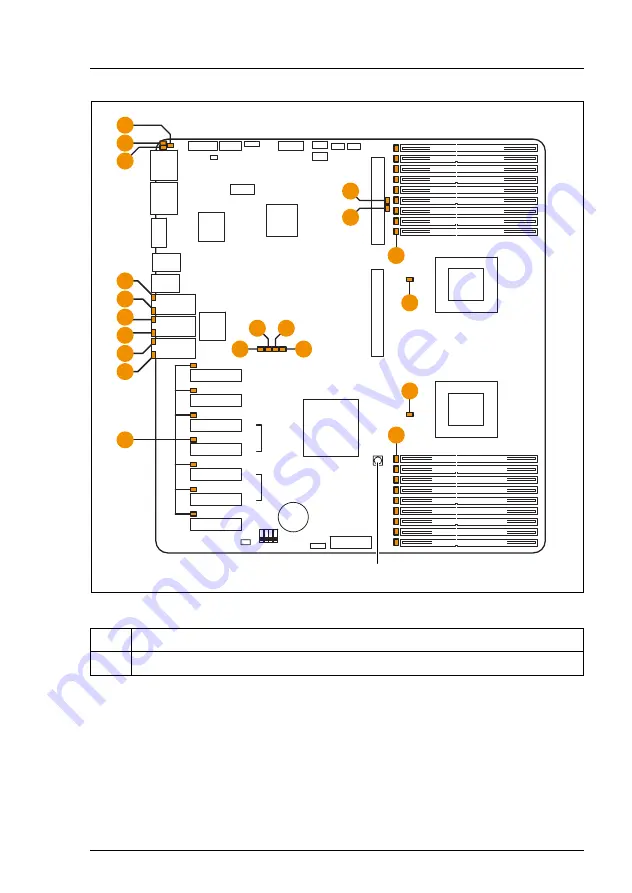
Figure 5: Indicators on the system board and CSS indicate button
LEDs A, B, C, D and E are visible from outside on the rear of the server. All the
other LEDs are only visible, if the cover of the server has been opened.
If the server has been powered off (power-plugs must be disconnected) it is
possible to indicate the faulty component by pressing the CSS indicate button.
No.
Description
1
CSS indicate button
DI
P
Switch
S
M
C
TRL
external
connectors
I
ndicate
C
SS
L
N
M
O
B
attery
VG
A
Slot
3
P
CI
e
Slot
4
P
CI
e
Slot
5
P
CI
e
Slot
6
P
CI
e
Slot
7
P
CI
e
Slot
1
P
CI
e
Slot
2
P
CI
e
Serial
1
Serial
2
US
B
1
/
2
US
B
3
/4
L
A
N
C
TRL
x4
x4
x4
x4
x4
x8
x8
x8
empty
x8
empty
F
D
E
D
E
D
E
L
A
N
1
L
A
N
2
Service
L
A
N
A
B
C
I
K
G
G
C
PU
1
C
PU
2
H
H
C
PU
1 DIMM 3A
C
PU
1 DIMM 2A
C
PU
1 DIMM 3C
C
PU
1 DIMM 1B
C
PU
1 DIMM 2B
C
PU
1 DIMM 3B
C
PU
1 DIMM 1A
C
PU
1 DIMM 1C
C
PU
1 DIMM 2C
C
PU
2 DIMM 1F
C
PU
2 DIMM 2F
C
PU
2 DIMM 1D
C
PU
2 DIMM 3E
C
PU
2 DIMM 2E
C
PU
2 DIMM 1E
C
PU
2 DIMM 3F
C
PU
2 DIMM 3D
C
PU
2 DIMM 2D
0
Summary of Contents for D2619-N
Page 6: ...Technical Manual D2619 N RX TX300 S6 ...
Page 8: ...Technical Manual D2619 N RX TX300 S6 Contents ...
Page 10: ...10 Technical Manual D2619 N RX TX300 S6 Notational conventions Introduction ...
Page 38: ...38 Technical Manual D2619 N RX TX300 S6 Settings Features ...
Page 40: ...40 Technical Manual D2619 N RX TX300 S6 Replacing the lithium battery ...


