background image

6 - English

Installing/removing the processor

Procedure

The processor socket is covered with a protective cap to protect the spring
contacts In the event of a warranty case, the mainboard can only be taken back
by Fujitsu Technology Solutions with the protective cap secured!

a

b

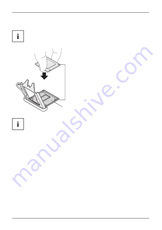
Remove the heat sink.

Press down the lever and unhook it.

Fold up the frame.

Remove the protective cap and keep it.

Hold the processor between your thumb
and index

fi

nger and insert it into the socket

(b) so that the marking of the processor is
aligned with the marking on the socket (a).

Press the lever downward until it is
hooked in again.

Please note that, depending on the heat sink used, different heat sink
mounts are required on the mainboard.

Depending on the con

fi

guration variant, you must pull a protective foil off the heat sink

or coat the heat sink with heat conducting paste before

fi

tting it.

Secure the heat sink - depending on the model - with four screws or push it into the mounts.

22

Fujitsu

Summary of Contents for D3654-B

Page 1: ...Mainboard Short Description Mainboard D3654 ...

Page 2: ...ound on the Internet at http www fujitsu com fts For driver updates go to http support ts fujitsu com download Should you have any technical questions please contact our Hotline Service Desk http support ts fujitsu com contact servicedesk Your sales partner Your sales office We hope you enjoy working with your new Fujitsu system ...

Page 3: ......

Page 4: ...jitsu Technology Solutions GmbH Mies van der Rohe Straße 8 80807 Munich Germany http www fujitsu com fts Copyright Fujitsu Technology Solutions GmbH 2018 All rights reserved Publication Date 10 2018 Order No A26361 D3654 Z320 1 7419 edition 1 ...

Page 5: ...AN 19V DC IN optional DP Displayport USB 2 0 USB 2 0 USB Type C USB 3 1 GEN 1 USB 3 1 GEN 1 DP Displayport USB 2 0 USB 3 1 GEN 1 USB 3 1 GEN 1 Power Button USB 3 1 x 1 Gen 1 USB TYP C RCV PWD Header D3654 A HDMI Connector DC IN LAN HDMI Connector DC IN LAN D3654 A C I O Shield Rear D3654 A D3654 A C I O Shield Front D3654 A C I O Shield Rear D3654 C Top side Channel A Slot 2 Channel B Slot 1 Fujit...

Page 6: ... Displayport USB 2 0 USB 3 1 GEN 1 USB 2 0 USB 3 1 GEN 1 Power Button USB Drive Power 5V only Mic Head phone USB 3 1 x 1 Gen 1 USB 3 1 x 1 Gen 1 USB TYP C Mic Power Button RCV PWD Header Front Panel HDMI Connector DC IN LAN D3654 B D3654 B I O Shield Rear D3654 B I O Shield Rear Front D3654 B Top side Channel A Slot 2 Channel B Slot 1 Fujitsu ...

Page 7: ...SATA 6 Gb s Ports1 1 1 1 Intel Smart Response Technology Yes Yes Yes eSATA support No No No PCIe Speed 2 0 2 0 2 0 Supported USB Speed USB2 0 USB3 1 Gen1 5 Gbit USB2 0 USB3 1 Gen1 5 Gbit USB2 0 USB3 1 Gen1 5 Gbit System FAN2 1 2 1 FAN Control Silent FAN LT Silent FAN LT Silent FAN LT TEMP Sensors Devices CPU PCH CPU PCH CPU PCH Onboard TEMP Sensors M 2 SSD CPU Regulator Memory slot M 2 WLAN M 2 SS...

Page 8: ...Access protection for disk drives USB Power Off Enable Disable USB Power via BIOS in shut down mode Low Power Active Mode optional Special sleep mode which replaces the conventional Windows sleep mode in order to significantly reduce the idle power consumption Low Power Active Mode is managed with the Workplace Power and Communication Settings utility which can be found in the Control Panel in the...

Page 9: ...Mainboard D3654 First time setup Deutsch 7 English 17 ...

Page 10: ......

Page 11: ...oards 3 Anschlüsse und Steckverbinder 4 Prozessor ein ausbauen 5 Technische Daten 5 Vorgehensweise 6 Hauptspeicher ein ausbauen 7 Betriebsanzeige 8 BIOS Update 9 BIOS Update unter Windows mit dem Programm DeskFlash 9 BIOS Update mit einem USB Stick 9 Fujitsu 7 ...

Page 12: ...indows sind registrierte oder nicht registrierte Marken der Microsoft Corporation in den USA und oder in anderen Ländern HDMI und High Definition Multimedia Interface sind Warenzeichen bzw eingetragene Warenzeichen der HDMI Licensing LLC s PCI EXPRESS und PCIE sind registrierte Marken der PCI SIG in den USA und in anderen Ländern SATA ist ein Produktname der SATA IO USB Type CTM und USB CTM sind W...

Page 13: ...ugruppen stecken oder ziehen Fassen Sie die Baugruppen nur am Rand an Berühren Sie keine Anschluss Stifte oder Leiterbahnen auf der Baugruppe Eine Übersicht der Leistungsmerkmale finden Sie im Datenblatt Besondere Merkmale Ihr Mainboard ist in verschiedenen Ausbaustufen erhältlich Abhängig von der Konfiguration Ihres Mainboards besitzt oder unterstützt das Mainboard bestimmte Merkmale In diesem Ha...

Page 14: ...en und Steckverbinder müssen nicht auf dem Mainboard vorhanden sein Externe Anschlüsse Die Position der externen Anschlüsse Ihres Mainboards finden Sie am Anfang des Handbuches LAN Anschluss RJ 45 DP Displayport Audioausgang HP Audioausgang Line out Buchse Typ A schwarz Universal Serial Bus USB 2 0 Buchse Typ A blau Universal Serial Bus USB 3 1 Gen 1 Mikrofonanschluss HDMI Anschluss 10 Fujitsu ...

Page 15: ... http www fujitsu com fts products Fassen Sie auf keinen Fall die Unterseite des Prozessors an Schon leichte Verunreinigungen wie Fett von der Haut können die Funktion des Prozessors beeinträchtigen oder den Prozessor zerstören Setzen Sie den Prozessor mit großer Sorgfalt in den Steckplatz da die Federkontakte des Steckplatzes sehr empfindlich sind und nicht verbogen werden dürfen Sind ein oder me...

Page 16: ...en Sie den Prozessor mit Daumen und Zeigefinger und stecken Sie ihn so in den Steckplatz b dass die Markierung des Prozessors mit der Markierung am Steckplatz von der Lage her übereinstimmt a Drücken Sie den Hebel nach unten bis er wieder einhakt Bitte beachten Sie dass je nach verwendetem Kühlkörper unterschiedliche Kühlkörperhalterungen auf dem Mainboard benötigt werden Je nach Ausbau Variante m...

Page 17: ...biniert werden Es dürfen nur ungepufferte DDR4 Speichermodule ohne ECC verwendet werden DDR4 Speichermodule müssen der DDR4 2133 DDR4 2400 oder DDR4 2666 Spezifikation entsprechen DDR4 2600 Speichermodule sind abwärtskompatibel und werden abhängig von der CPU betrieben Die maximale Systemperformance ist gegeben wenn in Channel A und in Channel B identische Speichermodule verwendet werden Abhängig ...

Page 18: ...System ist ausgeschaltet oder stromlos Leuchtet Das System ist in Betrieb Blinkt gleichmäßig 50 an 50 aus Das System befindet sich im Sleep Modus Blinkt ungleichmäßig 20 an 80 aus optional Das System befindet sich im Energiesparmodus Low Power Active Mode Blinkt 2x kurz nach Pause wiederholt Es liegt ein Fehler in der CPU Stromversorgung der CPU oder im BIOS vor 14 Fujitsu ...

Page 19: ...vers Utilities unter Flash BIOS oder Laden Sie die Update Datei für Flash BIOS Update Desk Flash Instant von unserer Internet Seite auf Ihren PC Führen Sie die Update Datei aus Folgen Sie den Bildschirmanweisungen BIOS Update mit einem USB Stick Halten Sie einen FAT32 formatierten USB Stick bereit Laden Sie die Zip Datei Admin package Compressed Flash Files von unserer Internet Seite auf Ihren PC ...

Page 20: ...10 Deutsch BIOS Update 16 Fujitsu ...

Page 21: ...nboard 3 Interfaces and connectors 4 Installing removing the processor 5 Technical data 5 Procedure 6 Installing removing main memory 7 Power indicator 8 BIOS Update 9 BIOS update under Windows with DeskFlash program 9 BIOS update using a USB stick 9 Fujitsu 17 ...

Page 22: ...Windows are registered or unregistered trademarks of the Microsoft Corporation in the USA and or in other countries HDMI and High Definition Multimedia Interface are trademarks or registered trademarks of HDMI Licensing LLC s PCI EXPRESS and PCIE are registered trade marks of the PCI SIG in the USA and in other countries SATA is a product name of the SATA IO USB type CTM and USB CTM are trademarks...

Page 23: ...s supply before inserting or removing boards Always hold boards by their edges Never touch connector pins or conductors on the board An overview of the features is provided in the data sheet Special features Your mainboard is available in different configuration levels Depending on the configuration your mainboard will be equipped with or provide support for certain features This manual describes ...

Page 24: ... connectors marked are not necessarily present on the mainboard External ports The location of the external connections of your mainboard is specified at the beginning of the manual LAN port RJ 45 DP DisplayPort Audio output HP Audio output Line out Socket type A black Universal Serial Bus USB 2 0 Socket type A blue Universal Serial Bus USB 3 1 Gen 1 Microphone port HDMI port 20 Fujitsu ...

Page 25: ...ted by this mainboard is available on the Internet at http www fujitsu com fts products Never touch the underside of the processor Even minor soiling such as grease from the skin can impair the processor s operation or destroy the processor Place the processor in the socket with extreme care as the spring contacts of the socket are very delicate and must not be bent If one or more spring contacts ...

Page 26: ... it Hold the processor between your thumb and index finger and insert it into the socket b so that the marking of the processor is aligned with the marking on the socket a Press the lever downward until it is hooked in again Please note that depending on the heat sink used different heat sink mounts are required on the mainboard Depending on the configuration variant you must pull a protective foi...

Page 27: ...acities can be combined Only unbuffered DDR4 memory modules without ECC may be used DDR4 memory modules must comply with the DDR4 2133 DDR4 2400 or DDR4 2666 specification DDR4 2600 memory modules are downward compatible and are operated depending on the CPU The maximum system performance is ensured when identical memory modules are used in Channel A and Channel B Depending on how the system is co...

Page 28: ...on Not lit The system is switched off or currentless Lit The system is in operation Flashes regularly 50 on 50 off The system is in sleep mode Flashes irregularly 20 on 80 off optional The system is in energy saving mode Low Power Active Mode Flashes 2x short repeated after a pause There is a fault in the CPU power supply the CPU or the BIOS 24 Fujitsu ...

Page 29: ... located on the Drivers Utilities data carrier under Flash BIOS or Download the Flash BIOS Update Desk Flash Instant update file from our website to your PC Run the update file Follow the on screen instructions BIOS update using a USB stick Have a FAT32 formatted USB stick ready Download the ZIP file Admin package Compressed Flash Files from our website to your PC Unzip the ZIP file and copy the f...

Reviews: