66
L i f e B o o k E S e r i e s – S e c t i o n F o u r
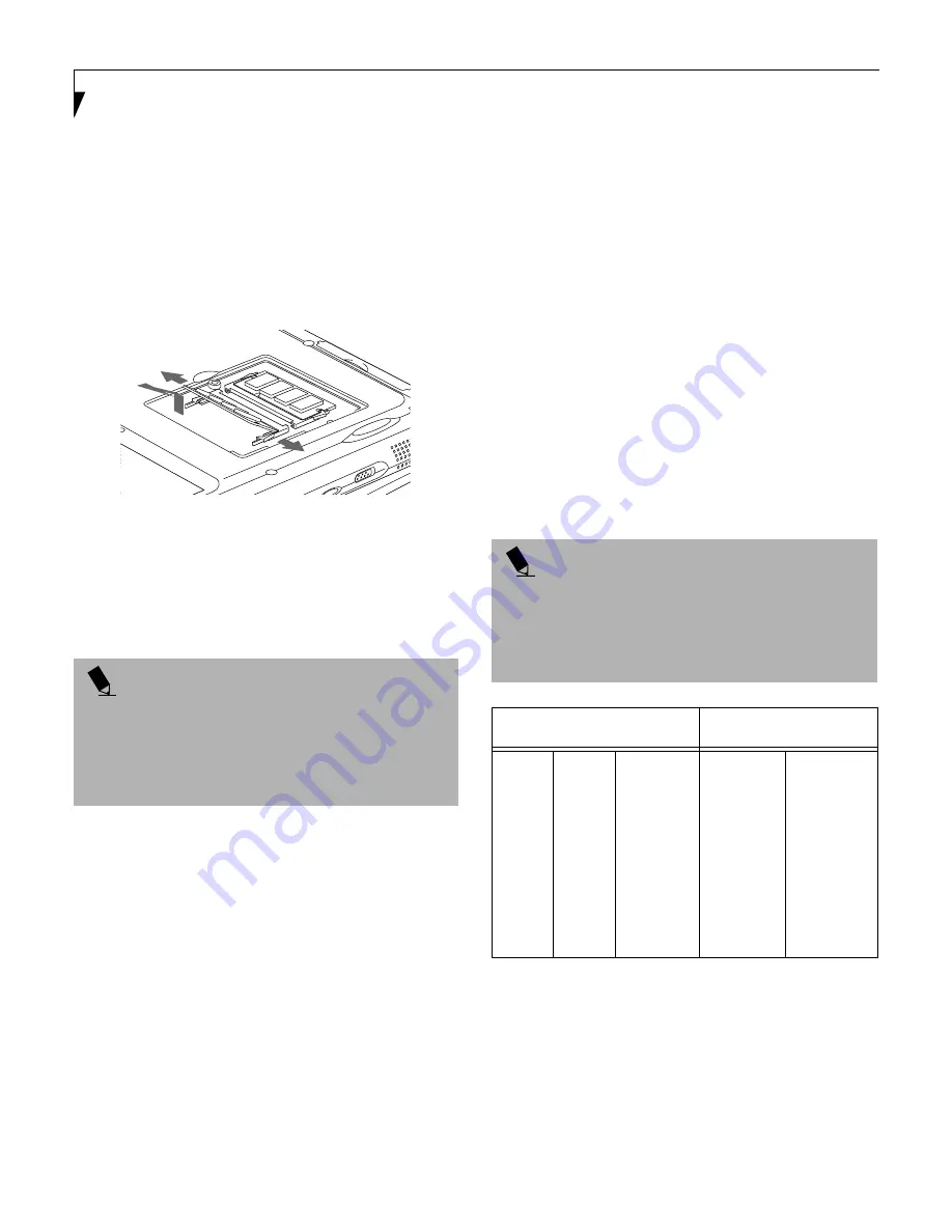
TO REMOVE A MEMORY UPGRADE MODULE:
1. Perform steps 1 through 5 of Installing a Memory
Upgrade Module.
2. Pull the clips sideways away from each side of the
memory upgrade module at the same time.
3. While holding the clips out, remove the module
from the slot by lifting it up and pulling towards the
rear of your notebook. (Figure 4-12)
Figure 4-12 Removing a Memory Upgrade Module
4. Store the memory upgrade module in a static
guarded sleeve.
5. Replace the cover by following steps 9 and 10 of
Installing a Memory Upgrade Module.
CHECKING THE COMPUTER RECOGNITION
OF NEW MEMORY CAPACITY
Once you have changed the system memory capacity
by either adding or removing a memory upgrade
module, be sure to check that your notebook has
recognized the change.
You can check the memory capacity by looking at the
main menu of the BIOS setup:
1. Turn on the power to your notebook using the
power switch.
2. Allow the system to start booting and press the key
once the Fujitsu logo appears on the screen. This will
open the main menu of the BIOS setup with the
current settings displayed. (See BIOS Setup Utility on
page 41 for more information)
The System Memory and the Extended Memory
capacity, as detected by your notebook during the Power
On Self Test (POST), are displayed at the bottom of the
main menu screen. The chart below shows you the
possible displays that can be shown on the main menu
screen. In the chart, Slot 1 is the original SDRAM
memory compartment while Slot 2 is the upgrade
compartment located in the center of your notebook.
P O I N T
After installing your added memory module, you must
complete the Resetting the Save-to-Disk Parameters
procedure in order for the Save-to-Disk mode to oper-
ate properly on your LifeBook.
(See Save-to-Disk Mode
on page 44 for more information)
P O I N T
If the total memory displayed is incorrect, check that
your memory upgrade module is properly installed. (If
the module is properly installed and the capacity is still
not correctly recognized, see the Troubleshooting sec-
tion starting on page 73)
Installed
Displayed
Slot 1
64MB
64MB
64MB
64MB
128MB
128MB
128MB
128MB
Slot 2
0
32MB
64MB
128MB
0
32MB
64MB
128MB
Total RAM
Installed
64MB
96MB
128MB
192MB
128MB
160MB
192MB
256MB
System
Memory
640K
640K
640K
640K
640K
640K
640K
640K
Extended
Memory
63MB
95MB
127MB
191MB
127MB
159MB
191MB
255MB
Summary of Contents for E Series
Page 1: ...S E R I E S E The Power And Choices You Demand User s Guide ...
Page 9: ...L i f e B o o k E S e r i e s ...
Page 11: ...2 L i f e B o o k E S e r i e s S e c t i o n O n e ...
Page 13: ...4 L i f e B o o k E S e r i e s S e c t i o n O n e ...
Page 45: ...36 L i f e B o o k E S e r i e s S e c t i o n T w o ...
Page 47: ...38 L i f e B o o k E S e r i e s S e c t i o n T h r e e ...
Page 57: ...48 L i f e B o o k E S e r i e s S e c t i o n T h r e e ...
Page 59: ...50 L i f e B o o k E S e r i e s S e c t i o n F o u r ...
Page 79: ...70 L i f e B o o k E S e r i e s S e c t i o n F o u r ...
Page 81: ...72 L i f e B o o k E S e r i e s S e c t i o n F i v e ...
Page 97: ...88 L i f e B o o k E S e r i e s S e c t i o n F i v e ...
Page 99: ...90 L i f e B o o k E S e r i e s S e c t i o n S i x ...
Page 103: ...94 L i f e B o o k E S e r i e s S e c t i o n S i x ...
Page 105: ...96 L i f e B o o k E S e r i e s S e c t i o n S e v e n ...
Page 109: ...100 L i f e B o o k E S e r i e s S e c t i o n S e v e n ...
Page 110: ...G l o s s a r y Section Eight Glossary ...
Page 111: ...L i f e B o o k E S e r i e s S e c t i o n E i g h t ...
Page 117: ...108 L i f e B o o k E S e r i e s S e c t i o n E i g h t ...


