14
INDOOR UNIT
FACTORY
PISTON
SEER RATING
OD UNIT
NOMINAL
TONS
REFRIGERANT
ORIFICE
SIZE
13
1.5
R410a 0.047
14
1.5 R410a 0.049
(-)F1P1821SPAN
0.047
13
1.5
R22
0.049
12
1.5
R22
0.051
10
1.5
R22
0.053
13
2
R410a 0.053
14
2 R410a 0.057
(-)F1P2421SPAN
0.053
13
2
R22
0.057
12
2
R22
0.061
10
2
R22
0.063
13
2.5
R410a 0.061
14
2.5 R410a 0.063
(-)F1P3024SPAN
0.061
13
2.5
R22
0.065
12
2.5
R22
0.065
10
2.5
R22
0.065
13
3
R410a 0.065
14
3 R410a 0.068
(-)F1P3624SPAN
0.065
13
3
R22
0.069
12
3
R22
0.070
10
3
R22
0.070
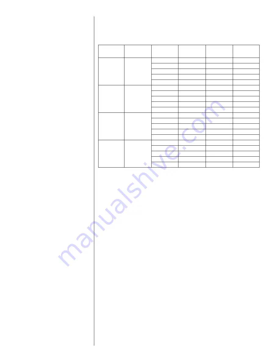
3.8 ORIFICE SIZE: (-)F1P*****P MODELS
(-)F1P*****P air-handlers are equipped with a fixed orifice (piston) sized for a typical 13
SEER R-410A outdoor unit. The piston must be changed if the outdoor unit has a higher
or lower efficiency or if the system is using R-22 as a refrigerant. The chart below shows
recommended orifice sizes for various efficiencies for R-410A and R-22.
The orifice is located in the indoor coil distributor body and can be accessed by
unscrewing the distributor body. Replacing the Teflon gasket is recommended when
changing the orifice to assure a leak free joint. Orifices and gaskets are available from
most local wholesale distributors.
3.9 REFRIGERANT LINE CONNECTIONS & CHARGING
3.9.1 PREPARATION
The coil is shipped with a low pressure (5-10 psig) charge of dry nitrogen which will be
released when the rubber plugs are removed. Leave the rubber plugs in the refrigerant
connection stubs on the air-handler until the refrigerant lines are ready to be brazed to
the refrigerant connection stubs to prevent contaminants from entering the coil. Clean
the ends of the tubing and coil connection stubs (inside and outside) with an alcohol
wipe before inserting the line set tubes into the coil connection stubs to assure a quality
leak-free braze joint.
Refer to the outdoor unit installation instructions for details on refrigerant line sizing and
installation. Be sure to follow long line length guidelines if they apply.
Route the refrigerant tubing in a manner than does not block service access to the front
of the air-handler.
3.9.2 LIQUID LINE FILTER DRIER
A new liquid filter drier must be installed every time any part of the system has been
open to the atmosphere, even if it’s for a short period of time. The filter drier should be
installed close to the air-handler for a system started up in the cooling mode and near
the outdoor unit for a heat pump system started up in the heating mode. This allows the
filter drier to catch any contaminants in the liquid line before they can enter the indoor or
outdoor TXV or piston inlet screen.
3.9.3 BRAZING
Air inside the tubing and coil should be displaced with dry nitrogen prior to the brazing
process to prevent the formation of harmful copper oxide inside the tubing. It is very
important not to pressurize the system with nitrogen while brazing or pin-hole leaks will
form in the braze joint. This is accomplished by removing the gauge port valve core on
one of the outdoor unit service valves to allow the pressure to be relieved as the heat-
ed nitrogen expands. Fill the system with dry nitrogen through the other service valve
gauge port and then turn the nitrogen flow off just before brazing is begun.


