MB89620 series
CHAPTER 7 8-BIT PWM TIMER
141
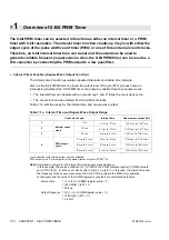
l
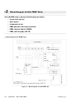
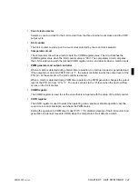
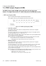
Count clock selector
Selects a count-up clock for the 8-bit counter from the three internal count clocks and the PWC
output cycle.
l
8-bit counter
The 8-bit counter counts-up on the count clock selected by the count clock selector.
l
Comparator circuit
The comparator circuit has a latch to hold the COMR register value. The circuit latches the
COMR register value when the 8-bit counter value is “00
H
”. The comparator circuit compares
the 8-bit counter value with the latched COMR register value, and detects when a match occurs.
l
PWM generator and output controller
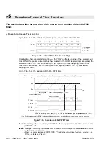
When a match is detected during interval timer operation, an interrupt request is generated and,
if the output pin control bit (CNTR: OE) is “1”, the output controller inverts the output level of the
PTO pin. At the same time, the 8-bit counter is cleared.
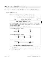
When a match is detected during PWM timer operation, the PWM generator changes the output
level of the PTO pin from “H” to “L”. The pin is set back to the “H” level when the next overflow
occurs on the 8-bit counter.
l
COMR register
The COMR register is used to set the value that is compared with the value of the 8-bit counter.
l
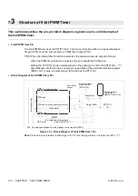
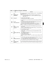
CNTR register
The CNTR register is used to select the operating mode, enable or disable operation, set the
count clock, control interrupts, and check the PWM status.
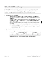
Setting the operation to PWM timer mode (P/TX = “0”) disables clearing of the 8-bit counter and
generation of interrupt requests (IRQ4) when the comparator circuit detects a match.
Summary of Contents for F2MC-8L MB89620 Series
Page 8: ......
Page 10: ...MB89620 series ...
Page 11: ...vi MB89620 series ...
Page 17: ...xii MB89620 series ...
Page 18: ...xvi MB89620 series ...
Page 30: ...MB89620 series CHAPTER 1 OVERVIEW 9 Memo ...
Page 34: ...MB89620 series CHAPTER 1 OVERVIEW 13 Memo ...
Page 42: ...MB89620 series CHAPTER 1 OVERVIEW 21 Memo ...
Page 49: ...28 CHAPTER 1 OVERVIEW MB89620 series ...
Page 62: ...MB89620 series CHAPTER 3 CPU 41 Memo ...
Page 78: ...MB89620 series CHAPTER 3 CPU 57 Memo ...
Page 82: ...MB89620 series CHAPTER 3 CPU 61 Memo ...
Page 86: ...MB89620 series CHAPTER 3 CPU 65 Memo ...
Page 90: ...MB89620 series CHAPTER 3 CPU 69 Memo ...
Page 96: ...MB89620 series CHAPTER 3 CPU 75 Memo ...
Page 122: ...MB89620 series CHAPTER 4 I O PORTS 101 Memo ...
Page 144: ...MB89620 series CHAPTER 5 TIMEBASE TIMER 123 Memo ...
Page 149: ...128 CHAPTER 5 TIMEBASE TIMER MB89620 series ...
Page 157: ...136 CHAPTER 6 WATCHDOG TIMER MB89620 series ...
Page 174: ...MB89620 series CHAPTER 7 8 BIT PWM TIMER 153 Memo ...
Page 177: ...156 CHAPTER 7 8 BIT PWM TIMER MB89620 series ...
Page 202: ...MB89620 series CHAPTER 9 16 BIT TIMER COUNTER 181 Memo ...
Page 217: ...196 CHAPTER 9 16 BIT TIMER COUNTER MB89620 series ...
Page 220: ...MB89620 series CHAPTER 10 8 BIT SERIAL I O SERIAL I O 1 AND SERIAL I O 2 199 Memo ...
Page 228: ...MB89620 series CHAPTER 10 8 BIT SERIAL I O SERIAL I O 1 AND SERIAL I O 2 207 Memo ...
Page 245: ...224 CHAPTER 10 8 BIT SERIAL I O SERIAL I O 1 AND SERIAL I O 2 MB89620 series ...
Page 266: ...MB89620 series CHAPTER 13 A D CONVERTER 245 13 Memo ...
Page 283: ...262 CHAPTER 13 A D CONVERTER MB89620 series ...
Page 289: ...268 CHAPTER 14 CLOCK MONITOR FUNCTION MB89620 series ...
Page 306: ...MB89620 series APPENDIX 285 APPEND Memo ...
Page 319: ...298 APPENDIX MB89620 series Memo ...
Page 321: ...2 ...
Page 354: ......

