MB89620 series
CHAPTER 7 8-BIT PWM TIMER
149
7.
6
Operation of PWM Timer Function
This section describes the operation of the PWM timer function of the 8-bit PWM timer.
n
Operation of PWM Timer Function
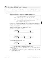
Figure 7.6a shows the settings required to operate as the PWM timer function.
Figure 7.6a PWM Timer Function Settings
On activation, the counter starts counting-up from “00
H
” on the rising edge of the selected count
clock. The PTO pin (PWM waveform) outputs an “H” level until the counter value matches the
value set in the COMR register. From the match until the counter value overflows (FF
H
→
00
H
),
the PTO pin outputs an “L” level.
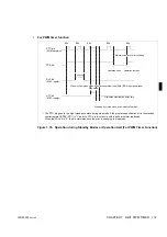
Figure 7.6b shows the PWM waveforms output from the PTO pin.
Figure 7.6b Example of PWM Waveform Output (PTO Pin)
Check:
Do not change the count clock cycle (CNTR: P1, P0) during operation of the PWM timer function
(CNTR: TPE = “1”).
Note:
When the PWM timer function is selected, the PTO pin maintains its existing level when the counter
is stopped (CNTR: TPE = “0”).
Bit 7
Bit 6
Bit 5
Bit 4
Bit 3
Bit 2
Bit 1
Bit 0
CNTR
P/TX
—
P1
P0
TPE
TIR
OE
TIE
1
1
×
1
×
COMR
Sets “H” width of pulse (compare value).
: Used bit
×
: Unused bit
1 : Set “1”.
For COMR register value of “00
H
” (duty ratio = 0%)
Counter value 00
H
H
L
H
L
H
L
00
H
00
H
Counter value
Counter value
PWM waveform
PWM waveform
PWM waveform
For COMR register value of “80
H
” (duty ratio = 50%)
For COMR register value of “FF
H
” (duty ratio = 99.6%)
FF
H
00
H
FF
H
00
H
FF
H
00
H
80
H
One count width
Summary of Contents for F2MC-8L MB89620 Series
Page 8: ......
Page 10: ...MB89620 series ...
Page 11: ...vi MB89620 series ...
Page 17: ...xii MB89620 series ...
Page 18: ...xvi MB89620 series ...
Page 30: ...MB89620 series CHAPTER 1 OVERVIEW 9 Memo ...
Page 34: ...MB89620 series CHAPTER 1 OVERVIEW 13 Memo ...
Page 42: ...MB89620 series CHAPTER 1 OVERVIEW 21 Memo ...
Page 49: ...28 CHAPTER 1 OVERVIEW MB89620 series ...
Page 62: ...MB89620 series CHAPTER 3 CPU 41 Memo ...
Page 78: ...MB89620 series CHAPTER 3 CPU 57 Memo ...
Page 82: ...MB89620 series CHAPTER 3 CPU 61 Memo ...
Page 86: ...MB89620 series CHAPTER 3 CPU 65 Memo ...
Page 90: ...MB89620 series CHAPTER 3 CPU 69 Memo ...
Page 96: ...MB89620 series CHAPTER 3 CPU 75 Memo ...
Page 122: ...MB89620 series CHAPTER 4 I O PORTS 101 Memo ...
Page 144: ...MB89620 series CHAPTER 5 TIMEBASE TIMER 123 Memo ...
Page 149: ...128 CHAPTER 5 TIMEBASE TIMER MB89620 series ...
Page 157: ...136 CHAPTER 6 WATCHDOG TIMER MB89620 series ...
Page 174: ...MB89620 series CHAPTER 7 8 BIT PWM TIMER 153 Memo ...
Page 177: ...156 CHAPTER 7 8 BIT PWM TIMER MB89620 series ...
Page 202: ...MB89620 series CHAPTER 9 16 BIT TIMER COUNTER 181 Memo ...
Page 217: ...196 CHAPTER 9 16 BIT TIMER COUNTER MB89620 series ...
Page 220: ...MB89620 series CHAPTER 10 8 BIT SERIAL I O SERIAL I O 1 AND SERIAL I O 2 199 Memo ...
Page 228: ...MB89620 series CHAPTER 10 8 BIT SERIAL I O SERIAL I O 1 AND SERIAL I O 2 207 Memo ...
Page 245: ...224 CHAPTER 10 8 BIT SERIAL I O SERIAL I O 1 AND SERIAL I O 2 MB89620 series ...
Page 266: ...MB89620 series CHAPTER 13 A D CONVERTER 245 13 Memo ...
Page 283: ...262 CHAPTER 13 A D CONVERTER MB89620 series ...
Page 289: ...268 CHAPTER 14 CLOCK MONITOR FUNCTION MB89620 series ...
Page 306: ...MB89620 series APPENDIX 285 APPEND Memo ...
Page 319: ...298 APPENDIX MB89620 series Memo ...
Page 321: ...2 ...
Page 354: ......

