background image

MB89620 series

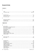
Keyword Index

301

IN

D

data shift direction  .......................................................................................................................................198
decimal adjustment instructions  ....................................................................................................................38
dedicated registers  ........................................................................................................................................36
direct addressing  ...........................................................................................................................................32
duty ratios  ....................................................................................................................................................139

E

eight bit, serial data of  .................................................................................................................................217
error  .............................................................................................................................................................259
external area ..................................................................................................................................................32
external bus mode  ...................................................................................................................................55, 76
external capacitor, connect ..........................................................................................................................258
external interrupt source, separate interrupt requests are generated for  ....................................................232
external reset .................................................................................................................................................52
external reset pin  ...........................................................................................................................................53
external shift clock  ...............................................................................................................................202, 208
external shift clock, waiting for input of, .......................................................................................................214
extra pointer ...................................................................................................................................................37

G

general-purpose register addressing .............................................................................................................34
general-purpose registers ..............................................................................................................................42

H

“H” and “L” widths of one cycle ....................................................................................................................139
halting operation during transfer ..................................................................................................................219
hold acknowledge ..........................................................................................................................................86
hold function  ..................................................................................................................................................86
holds the input voltage .................................................................................................................................247

I

I/O area ..........................................................................................................................................................32
idle state  ......................................................................................................................................................214
index register  .................................................................................................................................................37
input capture ................................................................................................................................................172
Instruction cycyle  ...........................................................................................................................................63
internal count clock ......................................................................................................................................124
internal reset sources  ....................................................................................................................................53
internal ROM/external bus mode ...................................................................................................................76
internal shift clock  ................................................................................................................................202, 208
interrupt enable flag .................................................................................................................................47, 74
interrupt handling time  ...................................................................................................................................49
interrupt level bits  ..........................................................................................................................................47
interrupt level priorities  ..................................................................................................................................39
interrupt level setting register  ............................................................................................................39, 47, 74
interrupt operation, procedure for  ..................................................................................................................46
interrupt priority ..............................................................................................................................................45
interrupt processing level ...............................................................................................................................44

Summary of Contents for F2MC-8L MB89620 Series

Page 1: ...FUJITSU SEMICONDUCTOR CONTROLLER MANUAL F2MC 8L 8 BIT MICROCONTROLLER MB89620 SERIES HARDWARE MANUAL CM25 10101 4E ...

Page 2: ...U Flexible Microcontroller n Configuration of This Manual This manual consists of the following 14 chapters Chapter 1 Overview Provides an overview of the features and functions of the MB89620 series Chapter 2 Handling Devices Describes points to note when using the MB89620 series Chapter 3 CPU Describes the functions of the MB89620 series CPU Chapter 4 I O Ports Describes the functions and operat...

Page 3: ... functions and operation of the MB89620 series buzzer output Chapter 12 External Interrupt Circuit Edge Describes the functions and operation of the MB89620 series external interrupt circuit Chapter 13 A D Converter Describes the functions and operation of the MB89620 series A D converter Chapter 14 Clock Monitor Function Describes the functions and operation of the MB89620 series clock monitor Th...

Page 4: ...wings described in this manual 3 The contents of this manual may not be transferred or copied without the express permission of Fujitsu 4 The products contained in this document are not intended for use with equipments which require extremely high reliability such as aerospace equipments undersea repeaters nuclear control systems or medical equipments for life support 5 Some of the products descri...

Page 5: ...their respective abbreviations l Sub heading index The sub headings in each section lines that start with n are collected together in the sub heading index The sub heading index provides a means of looking up information at a finer level of detail than the table of contents n Naming Conventions for Register Name and Pin Name l Examples for description of register name and bit name By writing 1 to ...

Page 6: ... summary Section title Higher level section Table title Figure title Chapter title Series title Check Points requiring check and prohibited items Always read checks Note Provides useful information for reference Reference Indicates an item or manual that should be referenced ...

Page 7: ...ct l Software required for development Checklist C compiler Only required when developing in C Assembler linker librarian Software simulator Only required when performing evaluation using the simulator Emulator debugger Only required when performing evaluation using the MB2140A series The model number for each software package differs depending on the operating system See the F2 MC development too...

Page 8: ......

Page 9: ...W HANDLING DEVICES CPU I O PORTS TIMEBASE TIMER WATCHDOG TIMER 8 BIT PWM TIMER PULSE WIDTH COUNT TIMER PWC 16 BIT TIMER COUNTER 8 BIT SERIAL I O SERIAL I O 1 AND SERIAL I O 2 BUZZER OUTPUT EXTERNAL INTERRUPT CIRCUIT EDGE A D CONVERTER CLOCK MONITOR FUNCTION APPENDIX INDEX ...

Page 10: ...MB89620 series ...

Page 11: ...vi MB89620 series ...

Page 12: ...nfiguration 36 Figure 3 2 1a Structure of Condition Code Register 38 Figure 3 2 1b Change of Carry Flag by Shift Instruction 38 Figure 3 2 2a Structure of Register Bank Pointer 40 Figure 3 2 2b Rule for Conversion of Actual Addresses of General Purpose Register Area 40 Figure 3 3 Register Bank Structure 42 Figure 3 4 1 Structure of Interrupt Level Setting Registers 45 Figure 3 4 2 Interrupt Proces...

Page 13: ...am of Port 3 Pin 99 Figure 4 5 Block Diagram of Port 4 Pin 105 Figure 4 6 Block Diagram of Port 5 Pin 109 Figure 4 7 Block Diagram of Port 6 Pin 112 Figure 4 8 Connection Example for an Eight Segment LED 116 CHAPTER 5 TIMEBASE TIMER 117 Figure 5 2 Block Diagram of Timebase Timer 119 Figure 5 3 Timebase Timer Control Register TBTC 120 Figure 5 5a Interval Timer Function Settings 124 Figure 5 5b Tim...

Page 14: ...0 Figure 8 5c Interval Timer Function One shot Timer Mode Settings 171 Figure 8 5d Operation in One shot Timer Mode 171 Figure 8 6a Pulse Width Measurement Function Settings 172 Figure 8 6b Example of H Width Measurement Using Pulse Width Measurement Function 172 Figure 8 6c Measuring Long Pulse Widths 173 Figure 8 7 Counter Operation during Standby Modes or Operation Halt 174 Figure 8 8 Error on ...

Page 15: ...on During Halt Internal Shift Clock 218 Figure 10 8d Operation in Sleep Mode External Shift Clock 219 Figure 10 8e Operation in Stop Mode External Shift Clock 219 Figure 10 8f Operation during Halt External Shift Clock 219 Figure 10 9 Idle State of Shift Clock 220 Figure 10 10a Connection Example for 8 bit Serial I O Interface between Two MB89620s 221 Figure 10 10b Bidirectional Serial I O Operati...

Page 16: ...ction 265 Figure 14 3 Block Diagram of P30 ADST CLKO Pin 266 Figure 14 4 Clock Output Control Register CLKE 267 APPENDIX 269 Figure B 1a Direct Addressing 274 Figure B 1b Extended Addressing 274 Figure B 1c Bit Direct Addressing 274 Figure B 1d Index Addressing 275 Figure B 1e Pointer Addressing 275 Figure B 1f General Purpose Register Addressing 275 Figure B 1g Immediate Addressing 275 Figure B 1...

Page 17: ...xii MB89620 series ...

Page 18: ...xvi MB89620 series ...

Page 19: ...egister and Vector Table for A D Converter Interrupt 255 CHAPTER 14 CLOCK MONITOR FUNCTION 263 Table 14 4 Clock Output Control Register CLKE Bits 267 APPENDIX 269 Table A I O Map 270 Table Ba Instruction List Symbols 272 Table Bb Instruction List Columns 273 Table B 1 Vector Table Addresses corresponding to vct 276 Table B 3a Transfer Instructions 280 Table B 3b Arithmetic Operation Instructions 2...

Page 20: ...Time for a 10 MHz source oscillation 130 Table 6 3 Watchdog Timer Control Register WDTC Bits 132 CHAPTER 7 8 BIT PWM TIMER 137 Table 7 1a Interval Time and Square Wave Output Range 138 Table 7 1b Available PWM Wave Cycle for PWM Timer Function 139 Table 7 3 1 PWM Control Register CNTR Bits 145 Table 7 4 Register and Vector Table for 8 bit PWM Timer Interrupt 147 CHAPTER 8 PULSE WIDTH COUNT TIMER P...

Page 21: ...Control Register STBC Bits 71 Table 3 7 5 Pin States in Standby Modes 73 Table 3 8 1a Mode Pin Setting 78 Table 3 8 1b Mode Pins and Mode Data 79 Table 3 8 2 External Bus Pin Functions in Each Mode 80 Table 3 8 3 External Bus Pin Control Register BCTR Bit 81 CHAPTER 4 I O PORTS 87 Table 4 1a Port Function 89 Table 4 1b Port Register 89 Table 4 2a Port 0 and 1 Pins 90 Table 4 2b Correspondence betw...

Page 22: ... basic specifications of the MB89620 series 1 1 MB89620 Series Features 2 1 2 MB89620 Series Product Lineup 4 1 3 Differences among Products 6 1 4 MB89620 Series Block Diagram 8 1 5 Pin Assignment 10 1 6 Package Dimensions 14 1 7 I O Pins and Pin Functions 22 ...

Page 23: ...ltiplication and division instructions 16 bit arithmetic operations Test and branch instructions Bit manipulation instructions etc l Four types of times 8 bit PWM timer also usable as an interval timer 8 bit pulse width count timer Continuous measurement capable applicable to remote control etc 16 bit timer counter 20 bit timebase timer l Two serial interfaces 8 bit serial I O 1 8 bit serial I O 2...

Page 24: ...ce functions external bus mode Including hold and ready functions l I O ports max 53 channels General purpose I O ports N ch open drain 8 Output only ports N ch open drain 8 General purpose I O ports CMOS 24 Output only ports CMOS 8 Input only ports 5 ...

Page 25: ... V to 6 0 V 1 Part number Parameter MB89P625 MB89P627 MB89P629 MB89W625 MB89W627 Classification One time PROM products EPROM products ROM size 16 K 8 bits Internal PROM programming with general purpose EPROM programmer 32 K 8 bits Internal PROM programming with general purpose EPROM programmer 32 K 8 bits Internal PROM programming with general purpose EPROM programmer 16 K 8 bits Internal PROM pro...

Page 26: ...put for count clock selectable 8 bit pulse width count timer 8 bit one shot timer operation underflow output capable operating clock cycle 0 4 µs to 12 8 µs 8 bit reload timer operation square wave output capable operating clock cycle 0 4 µs to 12 8 µs 8 bit pulse width measurement operation continuous measurement H pulse width L pulse width from to from to capable 16 bit timer counter 16 bit time...

Page 27: ...9PV620 and MB89627 starts from 8000H On the MB89P627 and MB89W627 addresses 8000H to 8005H comprise the option setting area option settings can be read by reading these addresses On the MB89PV620 and MB89627 addresses 8000H to 8005H could also be used as a program ROM However do not use these addresses in order to maintain compatibility of the MB89P627 and MB89W627 On the MB89P629 the program area...

Page 28: ...e options vary by the product Before using options check Appendix C Mask Options Take particular care on the following points A pull up resistor cannot be set for P40 to P47 on the MB89P625 MB89W625 MB89P627 MB89W627 and MB89P629 A pull up resistor is not selectable for P50 to P57 of all products when an A D converter is used Options are fixed on the MB89PV620 MB89V623 MB89V625 MB89T623 and MB89T6...

Page 29: ... 8 bit PWM timer 8 bit pulse width count timer 16 bit timer counter 8 bit serial I O 1 Port 3 CMOS I O port 8 bit serial I O 2 Buzzer output Port 4 Port 5 8 bit A D converter External interrupt Port 6 Input only port CLKO output function MB89628R MB89629R and MB89P629 only X0 X1 RST P00 AD0 to P07 AD7 P10 A08 to P17 A15 MOD0 MOD1 P27 ALE P26 RD P25 WR P24 CLK P23 RDY P22 HRQ P21 HAK P20 BUFC P37 P...

Page 30: ...MB89620 series CHAPTER 1 OVERVIEW 9 Memo ...

Page 31: ...P31 SCK1 P30 ADST CLKO VSS P00 AD0 P01 AD1 P02 AD2 P03 AD3 P04 AD4 P05 AD5 P06 AD6 P07 AD7 P10 A08 P11 A09 P12 A10 P13 A11 P14 A12 P15 A13 P16 A14 P17 A15 P20 BUFC P21 HAK P22 HRQ P23 RDY P24 CLK P25 WR P26 RD P27 ALE Top view CLKO output function MB89628R MB89629R and MB89P629 only 1 2 3 4 5 6 7 8 9 10 11 12 13 14 15 16 17 18 19 20 21 22 23 24 25 26 27 28 29 30 31 32 64 63 62 61 60 59 58 57 56 55...

Page 32: ... X0 X1 V SS P27 ALE P26 RD P25 WR P24 CLK P23 RDY P22 HRQ P21 HAK P20 BUFC 17 18 19 20 21 22 23 24 25 26 27 28 29 30 31 32 P00 AD0 P01 AD1 P02 AD2 P03 AD3 P04 AD4 P05 AD5 P06 AD6 P07 AD7 P10 A08 P11 A09 P12 A10 P13 A11 P14 A12 P15 A13 P16 A14 P17 A15 48 47 46 45 44 43 42 41 40 39 38 37 36 35 34 33 P45 SCK2 P44 BZ P43 P42 P41 P40 P37 PTO P36 WTO V CC P35 PWC P34 EC P33 SI1 P32 SO1 P31 SCK1 P30 ADST...

Page 33: ...5 SCK2 P46 SO2 P47 SI2 P50 AN0 P51 AN1 P52 AN2 P53 AN3 P54 AN4 P55 AN5 P56 AN6 P57 AN7 AVCC AVR AVSS P60 INT0 P61 INT1 P62 INT2 P63 INT3 P64 1 2 3 4 5 6 7 8 9 10 11 12 13 14 15 16 17 18 19 P30 ADST CLKO 1 VSS P00 AD0 P01 AD1 P02 AD2 P03 AD3 P04 AD4 P05 AD5 P06 AD6 P07 AD7 P10 A08 P11 A09 P12 A10 P13 A11 P14 A12 P15 A13 P16 A14 P17 A15 P20 BUFC 51 50 49 48 47 46 45 44 43 42 41 40 39 38 37 36 35 34 ...

Page 34: ...MB89620 series CHAPTER 1 OVERVIEW 13 Memo ...

Page 35: ...le for the MB89620 series Figures 1 6a to 1 6g show the package dimensions n DIP 64P M01 Package Dimensions Figure 1 6a DIP 64P M01 Package Dimensions Lead pitch Row spacing Sealing method Plastic mold 70 mil 750 mil 64 pin Plastic SH DIP Dimensions in mm inches 64 pin Plastic SH DIP DIP 64P M01 ...

Page 36: ...ERVIEW 15 n DIP 64C A06 Package Dimensions Figure 1 6b DIP 64C A06 Package Dimensions Lead pitch Row spacing Sealing method Metal seal 70 mil 750 mil 64 pin Ceramic SH DIP Dimensions in mm inches 64 pin Ceramic SH DIP DIP 64C A06 ...

Page 37: ...ure 1 6c FPT 64P M03 Package Dimensions 64 pin Plastic SQFP FPT 64P M03 Dimensions in mm inches Lead pitch Package width length Lead shape Sealing method 0 50 mm 10 10 mm Gull wing Plastic mold 64 pin Plastic SQFP FPT 64P M03 Mounted height 1995 FUJITSU LIMITED F 64009S 2C 4 ...

Page 38: ...s Figure 1 6d FPT 64P M06 Package Dimensions 64 pin Plastic QFP Lead pitch Package width length Lead shape Sealing method Length of flat section of pin 1 00 mm 14 20 mm Gull wing Plastic mold 1 20 mm 64 pin Plastic QFP FPT 64P M06 Dimensions in mm inches Mounted height ...

Page 39: ...9 Package Dimensions Figure 1 6e FPT 64P M09 Package Dimensions 64 pin Plastic QFP Dimensions in mm inches Lead pitch Package width length Lead shape Sealing method 0 65 mm 12 12 mm Gull wing Plastic mold 64 pin Plastic QFP FPT 64P M09 Mounted height ...

Page 40: ... 64C P02 Package Dimensions Figure 1 6f MDP 64C P02 Package Dimensions 64 pin Ceramic MDIP Dimensions in mm inches Lead pitch Row spacing Motherboard material Mountedsocket material 70 mil 750 mil Ceramic Plastic 64 pin Ceramic MDIP MDP 64C P02 ...

Page 41: ...64C P01 Package Dimensions Figure 1 6g MQP 64C P01 Package Dimensions 64 pin Ceramic MQFP Dimensions in mm inches Lead pitch Lead shape Motherboard material Mountedsocket material 1 00 mm Straight Ceramic Plastic 64 pin Ceramic MQFP MQP 64C P01 ...

Page 42: ...MB89620 series CHAPTER 1 OVERVIEW 21 Memo ...

Page 43: ... an internal reset reguest optional The internal circuit is initialized by the input of L 56 to 49 49 to 42 48 to 41 P00 AD0 to P07 AD7 D General purpose I O ports When an external bus is used these ports function as multiplex pins of lower address output and data I O 48 to 41 41 to 34 40 to 33 P10 A08 to P17 A15 D General purpose I O ports When an external bus is used these ports function as uppe...

Page 44: ...This port is a hysteresis input type 59 52 51 P31 SCK1 E General purpose I O port Also serves as the clock I O for the 8 bit serial I O 1 This port is a hysteresis input type 60 53 52 P32 SO1 E General purpose I O port Also serves as the data output for the 8 bit serial I O 1 This port is a hysteresis input type 61 54 53 P33 SI1 E General purpose I O port Also serves as the data input for the 8 bi...

Page 45: ...rpose I O port Also serves as the data output for the serial I O 2 This port is a hysteresis input type 10 3 2 P47 SI2 G N ch open drain type general purpose I O port Also serves as the data input for the serial I O 2 This port is a hysteresis input type 11 to 18 4 to 11 3 to 10 P50 AN0 to P57 AN7 H N ch open drain type general purpose output ports Also serve as the analog input for the A D conver...

Page 46: ...0 O Address output pins 75 76 77 77 78 79 O1 O2 O3 I Data input pins 78 80 VSS O Power supply GND pin 79 80 81 82 83 82 83 84 85 86 O4 O5 O6 O7 O8 I Data input pins 84 87 CE O ROM chip enable pin Outputs H during standby 85 88 A10 O Address output pin 86 89 OE O ROM output enable pin Outputs L at all times 87 88 89 91 92 93 A11 A9 A8 O Address output pins 90 94 A13 O 91 95 A14 O 92 96 VCC O EPROM ...

Page 47: ...f approximately 1 MΩ 5 0 V B C At an output pull up resistor P ch of approximately 50 kΩ 5 0 V Hysteresis input D CMOS output CMOS input Pull up resistor optional except P22 and P23 Approximately 50 kΩ 5 0 V E CMOS output Hysteresis input Pull up resistor optional Approximately 50 kΩ 5 0 V X1 X0 N ch P ch P ch N ch P ch N ch R P ch N ch R P ch N ch R ...

Page 48: ... F CMOS output G N ch open drain output Hysteresis input Pull up resistor optional The MB89623 MB89625 MB89626 MB89627 MB89628R and MB89629R only Approximately 50 kΩ 5 0 V H N ch open drain output Analog input A D converter Pull up resistor optional Pull up disabled when used as an analog input Approximately 50 kΩ 5 0 V I Hysteresis input Pull up resistor optional Approximately 50 kΩ 5 0 V P ch N ...

Page 49: ...28 CHAPTER 1 OVERVIEW MB89620 series ...

Page 50: ... important A rapid fluctuation of VCC power supply voltage could cause malfunctions even if it occurs within the operation assurance range of the voltage As stabilization guidelines it is recommended to control power so that VCC ripple fluctuations P P value will be less than 10 of the standard VCC value at the commercial frequency 50 to 60 Hz and the transient fluctuation rate will be less than 0...

Page 51: ...CHAPTER 2 HANDLING DEVICES This chapter describes points to note when using the general purpose single chip microcontroller 2 1 Notes on Handling Devices 30 ...

Page 52: ...s the functions and operation of the CPU 3 1 Memory Space 32 3 2 Dedicated Registers 36 3 3 General purpose Registers 42 3 4 Interrupts 44 3 5 Resets 52 3 6 Clocks 58 3 7 Standby Modes Low power Consumption 66 3 8 Memory Access Modes 76 ...

Page 53: ...es between 100H and 1FFH can be used as the general purpose register area restrictions apply for some products The contents of RAM is indeterminate after a reset l ROM area Internal ROM is provided as an internal program area The internal ROM size differs between products Setting the memory access mode to external ROM mode enables internal ROM to be disconnected and set as an external area Address...

Page 54: ...0180H E000H 0280H C000H 0000H 0080H 0100H 0200H 0C80H A000H FFC0H FFFFH 0000H 0080H 0100H 0200H 0C80H 8000H FFC0H FFFFH 0000H 0080H 0100H 0200H 1080H FFC0H FFFFH 8007H 8000H 8007H 1 The ROM area is an external area depending on the mode The MB89T623 MB89T625 MB89V623 and MB89V625 cannot use internal ROM 2 Since addresses 8000H to 8005H for the MB89P627 and MB89W627 comprise an option area do not u...

Page 55: ...ters for details See Section 3 8 Memory Access Modes for details on external bus mode n Vector Table Area Addresses FFC0H to FFFFH Used as the vector table for the vector call instruction interrupts and resets The vector table is allocated at the top of the ROM area The start address of the corresponding processing routine is set as data at each vector table address Table 3 1 1 lists the vector ta...

Page 56: ...g the operation code instruction and the lower byte at the next address The byte ordering applies to both 16 bit immediate data and operands that specify a memory address Figure 3 1 2b shows how 16 bit data is stored in an instruction Figure 3 1 2b Byte Order of 16 bit Data in an Instruction n Storing 16 bit Data on Stack The same byte order applies when saving 16 bit register data on the stack du...

Page 57: ...eration register The accumulator is used to perform arithmetic operations and data transfers with data in memory or in other registers such as the temporary accumulator T The content of the accumulator can be treated as either word 16 bit or byte 8 bit data Only the lower 8 bits AL of the accumulator are used for byte arithmetic operations or transfers In this case the upper 8 bits AH remain uncha...

Page 58: ...ed offset value to the index address generates the memory address for data access The content of the index register after a reset is indeterminate l Extra pointer EP The extra pointer is a 16 bit register used to hold a memory address for data access The content of the extra pointer after a reset is indeterminate l Stack pointer SP The stack pointer is a 16 bit register used to hold the address re...

Page 59: ...N Set if the most significant bit MSB is set to 1 as a result of an arithmetic operation Cleared when the bit is set to 0 l Zero flag Z Set when an arithmetic operation results in 0 Cleared otherwise l Overflow flag V Set if the complement on 2 overflows as a result of an arithmetic operation Reset if the overflow does not occur l Carry flag C Set when a carry from bit 7 or borrow to bit 7 occurs ...

Page 60: ...y the SETI instruction and clear to 0 by the CLRI instruction l Interrupt level bits IL1 IL0 These bits indicate the level of the interrupt currently being accepted by the CPU The value is compared with the interrupt level setting registers ILR1 to ILR3 which have a setting for each peripheral function interrupt request IRQ0 to IRQB Given that the interrupt enable flag is enabled I 1 the CPU only ...

Page 61: ... bank in the RAM area that is used for general purpose registers A total of 32 register banks are available A register bank is specified by setting a value between 0 and 31 in the upper 5 bits of the register bank pointer Each register bank contains eight 8 bit general purpose registers Registers are specified by the lower 3 bits of the operation codes Using the register bank pointer the addresses...

Page 62: ...MB89620 series CHAPTER 3 CPU 41 Memo ...

Page 63: ...d up to a total of 32 banks However the number of banks available for general purpose registers is limited on some products if internal RAM only is used The register bank currently in use is specified by the register bank pointer RP The lower three bits of the operation code specify general purpose register 0 R0 to general purpose register 7 R7 Figure 3 3 shows the register bank structure Figure 3...

Page 64: ...written to unintentionally by other routines The interrupt processing routine only needs to specify its dedicated register bank at the start of the routine to effectively save the general purpose registers in use prior to the interrupt Therefore saving the general purpose registers to the stack or other memory location is not necessary This allows high speed interrupt handling while maintaining si...

Page 65: ... be set for each interrupt request in the interrupt level setting registers ILR1 ILR2 ILR3 Three levels are available If an interrupt request with the same or lower level occurs during execution of an interrupt processing routine the latter interrupt is not normally processed until the current interrupt processing routine completes If interrupt requests set with the same level occur simultaneously...

Page 66: ...etting bits are compared with the interrupt level bits in the condition code register CCR IL1 ILR0 The CPU does not accept interrupt requests set to interrupt level 3 Table 3 4 1 shows the relationship between the interrupt level setting bits and the interrupt levels Note The interrupt level bits in the condition code register CCR IL1 IL0 are normally 11 during main program execution Check As the ...

Page 67: ...with the same level then check the interrupt enable flag CCR I Figure 3 4 2 shows the interrupt processing Figure 3 4 2 Interrupt Processing START Initialize peripheral Is an interrupt request present at the peripheral Is interrupt request output enabled for the peripheral Check the interrupt priority level and transfer the level to the CPU Compare the level with the IL bits in PS Is the level hig...

Page 68: ...el bits in the condition code register CCR IL1 IL0 the CPU checks the interrupt enable flag CCR I and receives the interrupt if interrupts are enabled CCR I 1 6 The CPU saves the contents of the program counter PC and program status PS on the stack reads the top address of the interrupt processing routine from the interrupt vector table for the interrupt updates the interrupt level bits in the con...

Page 69: ...rrupt level bits in the condition code register CCR IL1 IL0 are automatically set to the same value as the interrupt level setting register ILR1 ILR2 ILR3 corresponding to the timer interrupt level 2 in this example If the interrupt request set to higher interrupt level level 1 in this example occurs at this time the interrupt processing has priority To temporarily disable multiple interrupts duri...

Page 70: ... has the longest instruction cycles 21 instruction cycles l Interrupt handling time Nine instruction cycles are required to perform the following preparation for interrupt processing after the CPU accepts an interrupt request Save the program counter PC and program status PS Set the top address of the interrupt processing routine the interrupt vector in the PC Update the interrupt level bits PS CC...

Page 71: ... execution of the interrupt return instruction RETI at the completion of interrupt processing the CPU performs the opposite processing to interrupt initiation restoring first the program status PS and then the program counter PC from the stack This returns the PS and PC to their states immediately prior to the start of the interrupt Check The CPU does not automatically save the accumulator A or te...

Page 72: ...RAM and allocating data areas upwards from the bottom RAM address is recommended Figure 3 4 6 shows the example of stack area setting Figure 3 4 6 Stack Area for Interrupt Processing Note The stack area is used in the downward direction starting from a high address by functions such as interrupts subroutine calls and the PUSHW instruction Instructions such as return instructions RETI RET and the P...

Page 73: ...et bit in the standby control register STBC RST generates a four instruction cycle reset The software reset does not wait for the oscillation stabilization delay time l Watchdog reset The watchdog reset generates a four instruction cycle reset if data is not written to the watchdog timer control register WDTC within a fixed time after the watchdog timer starts The watchdog reset does not wait for ...

Page 74: ...roducts with power on reset the external reset input is sampled on the internal clock except when in stop mode Therefore reset inputs are not accepted if the source oscillation is halted Products without power on reset accept reset inputs asynchronous with the internal clock Initialization of the internal circuit requires a clock Especially when an external clock is used a clock is needed to be in...

Page 75: ...on the contents of the RAM address cannot be assured n Overview of Reset Operation Figure 3 5 2 Reset Operation Flowchart During reset Mode fetch reset operation Normal operation RUN state Software reset Watchdog reset NO NO NO External reset input Power on reset selected YES YES YES Power on or stop mode Oscillation stabilization delay reset state Wakes up from external Fetch mode data Fetch rese...

Page 76: ...bilization Delay Reset State On products with power on reset the reset operation for a power on reset or external reset in stop mode starts after the oscillation stabilization delay time determined by the timebase timer If the CPU has not waked up from the external reset input when the delay time completes the reset operation does not start until the CPU wakes up from external reset As the oscilla...

Page 77: ...H level n Pin States after Reading Mode Data Ports 0 and 1 become available as general purpose I O ports when the mode data is 00H single chip mode However the pins remain in the high impedance state immediately after reading the mode data Pins with a pull up resistor optional go to the H level Port 2 can be used as an output only port Output is enabled and the ports output the L level immediately...

Page 78: ...MB89620 series CHAPTER 3 CPU 57 Memo ...

Page 79: ...ntroller controls the oscillation and supply of the clock signals according to the standby modes n Clock Supply Map Oscillation of a clock and its supply to the CPU and peripheral circuit peripheral functions are controlled by the clock controller according to the standby modes sleep stop Divide by n output derived from the free run counter is supplied to the peripheral functions some of the perip...

Page 80: ...ply to peripheral circuit Stop mode Divide by four Supply to the CPU 1 tinst Clock controller ADST CLKO Pin X1 Pin X0 Oscillation controlier FC The clock monitor function CLKO output function is available on the MB89628R MB89629R and MB89P629 only Frequency for the resonator or external clock source oscillation Continuous activation WTO PCR2 TO Watchdog timer 8 bit PWM timer 8 bit pulse width coun...

Page 81: ...6 1a Connection Example for Crystal or Ceramic Resonator Note A piezoelectric resonator FAR series that contains the external capacitors can also be used See the Data Sheet for details l External clock Connect an external clock to the X0 pin and leave the X1 pin open as shown in Figure 3 6 1b Figure 3 6 1b Connection Example for External Clock X0 X1 C1 C2 MB89620 series X0 X1 When using an externa...

Page 82: ...MB89620 series CHAPTER 3 CPU 61 Memo ...

Page 83: ...s the block diagram of the clock controller Figure 3 6 2 Block Diagram of Clock Controller Divide by four Divide by two STP SLP SPL RST STBC Oscillator Clock controller Stop of supply to the CPU 218 FC 214 FC From timebase timer Pin state Sleep mode Stop mode Clock for timebase timer Supply to the CPU 1 tinst FC Source oscillation tinst Instruction cycle divide by four source oscillation Enable FC...

Page 84: ...k supply stop signal in the oscillation stabilization delay time selector is released l Oscillation stabilization delay time selector This register selector selects two types of the oscillation stabilization delay time optional generated from the timebase timer and outputs the time as the clock supply stop signal to the CPU l STBC register This register controls changing from normal operation RUN ...

Page 85: ... resonator type crystal ceramic etc connected to the clock generator Consequently it is necessary to select an oscillation stabilization delay time that matches the type of oscillator being used The oscillation stabilization delay time is optional The oscillation stabilization delay time is the time from when the counter starts counting up from zero until an overflow occurs on the specified bit Pr...

Page 86: ...MB89620 series CHAPTER 3 CPU 65 Memo ...

Page 87: ...xcept the external interrupt and stops also the source oscillation n Standby Mode Operating States 1 High impedance Pins with a pull up resistor optional go to the H level 2 During an oscillation stabilization delay initiated by an external interrupt pins go to their states prior to entering stop mode Pins go to their reset states during an oscillation stabilization delay initiated by a reset See ...

Page 88: ... The CPU does not change to sleep mode even after completion of the interrupt processing l Wake up from sleep mode A reset or an interrupt from a peripheral function wakes up the CPU from sleep mode If a reset occurs during sleep mode the CPU wakes up from sleep mode and the reset operation also initializes the pin states If an interrupt request with an interrupt level higher than 11 occurs from a...

Page 89: ...occurs during stop mode on a product with power on reset the reset operation starts after the oscillation stabilization delay time Products without power on reset do not require for the oscillation stabilization delay time after a reset in stop mode or at power on The reset initializes pin states If an interrupt request with an interrupt level higher than 11 occurs from an external interrupt circu...

Page 90: ...MB89620 series CHAPTER 3 CPU 69 Memo ...

Page 91: ...H STP SLP SPL RST 0001XXXXB W W R W W RST Software reset bit Read Write 0 Generates a reset signal for four instruction cycles 1 Reading always returns 1 No effect on operation SPL Pin state specification bit 0 External pins hold their states prior to entering stop mode 1 External pins go to high impedance state on entering stop mode SLP Sleep bit Read Write 0 Reading always returns 0 No effect on...

Page 92: ... specification bit Specifies the states of the external pins during stop mode Writing 0 to this bit specifies that external pins hold their states levels on changing to stop mode Writing 1 to this bit specifies that external pins go to high impedance state on entering stop mode Pins with a pull up resistor optional go to the H level Initialized to 0 by a reset Bit 4 RST Software reset bit Specifie...

Page 93: ... multiple 3 Change to sleep mode by setting the standby control register STBC SLP 1 4 External reset input 5 Change to stop mode by setting the standby control register STBC STP 1 6 Interrupt request 7 External interrupt request 8 9 Timebase timer overflow oscillation stabilization delay time complete 10 11 External reset input Power on reset 11 9 8 7 1 2 4 3 6 5 Power on Oscillation stabilization...

Page 94: ...mode External bus mode Single chip mode External bus mode SPL 0 2 SPL 1 2 SPL 0 2 SPL 1 2 P00 AD0 to P07 AD7 Hold Data output 5 Hold Hi z 1 4 Data output 5 Hi z 1 4 P10 A08 to P17 A15 Address output 6 Address output 6 X0 Oscillator input Oscillator input Hi z 1 Hi z 1 Hi z 1 Hi z 1 X1 Oscillator output Oscillator output H output H output H output H output MOD0 MOD1 Mode input Mode input Mode input...

Page 95: ... from a standby mode the CPU performs the normal interrupt operations If the level set in the interrupt level setting register ILR1 to ILR3 corresponding to the interrupt request is higher than the interrupt level bits in the condition code register CCR IL1 IL0 and if the interrupt enable flag is enabled CCR I 1 the CPU branches to the interrupt processing routine If the interrupt is not accepted ...

Page 96: ...MB89620 series CHAPTER 3 CPU 75 Memo ...

Page 97: ...ilarly single chip mode and internal ROM external bus mode are not available on products that use external ROM only For details see Section 3 1 Memory Space n External ROM Mode External bus mode is enabled in external ROM mode and the internal ROM area is disconnected to become an external area External memory and other devices are accessed using the external bus n Internal ROM External Bus Mode E...

Page 98: ... access is used l External access Used to access externally connected devices such as RAM ROM or peripheral functions using the external bus Internal access is still available for internal I O and RAM areas even when external bus mode is enabled External bus mode Single chip mode External ROM mode Internal ROM external bus mode Internal I O area Internal RAM area Internal I O area Internal RAM are...

Page 99: ...r external bus mode external ROM mode or internal ROM external bus mode Figure 3 8 1a shows the structure of the mode data Figure 3 8 1a Mode Data Structure Check When selecting external ROM mode always specify external bus mode for the mode data Set the mode pins and mode data for single chip mode on products that support single chip mode only Table 3 8 1a Mode Pin Setting Pin state Description M...

Page 100: ...de data Set I O pin functions for program execution RUN Reset source generated Use external bus Do not use external bus Mode pins MOD0 MOD1 Read mode data from external ROM Read mode data from internal ROM All I O pins are high impedance Reset active Reset active Fetch mode data and reset vector from external ROM Fetch mode data and reset vector from internal ROM Address data RD WR ALE CLK RDY and...

Page 101: ... the output write direction and an L level indicates the input read direction P21 HAK P21 HAK Hold acknowledge output The signal indicates that the CPU has released the external bus in response to a hold request input HRQ from an external peripheral function An L level indicates that the external peripheral function can use the bus P22 HRQ P22 HRQ Hold request input The signal requests the CPU to ...

Page 102: ... register BCTR Table 3 8 3 External Bus Pin Control Register BCTR Bit Bit Function Bit 7 Bit 6 Bit 5 Bit 4 Bit 3 Bit 2 Unused bits The read value is indeterminate Writing has no effect on the operation Bit 1 HLD Hold enable bit Selects the operation of the P21 and P22 pins in external bus mode Writing 0 to this bit specifies the P21 and P22 pins to function as output only ports Writing 1 specifies...

Page 103: ...dress latch enable signal output from the ALE pin Reading is synchronized with the read strobe signal output from the RD pin and the read data is applied to the data pins Writing is synchronized with the write strobe signal output from the WR pin and completes when the data output on the data pins is read by the external memory or others The buffer control output BUFC signal is used when an extern...

Page 104: ...connected to the BUFC pin when using the hold function Also the AD0 to AD7 A08 to A15 and ALE signals are output during internal access but the RD WR and BUFC pins output an H level Figure 3 8 4b shows the example of connecting external memory and a peripheral function Figure 3 8 4b Example of Connecting External Memory and Peripheral Function D Q G OC A B DIR G Address decoder Address decoder Add...

Page 105: ...be established at the L level before this timing The CPU wakes up from the ready operation by externally setting the RDY pin to the H level and the bus cycle is complete The CPU ignores the RDY pin state when accessing to an internal area internal access Pull up the RDY pin if not using the ready function in external bus mode Figure 3 8 5a shows the ready operation Figure 3 8 5a Ready Operation n ...

Page 106: ...g edge of the address latch enable signal ALE When the ALE signal goes to the L level the shift register shifts in sync with the CLK signal in the order H G F etc This successively outputs a series of L levels from QH where the number of L levels output is the number of L levels loaded from the shift inputs By connecting this output signal to the RDY pin the CPU extends the bus cycle while the L l...

Page 107: ...a dead cycle the CPU outputs an L level from the hold acknowledge HAK pin to notify that it has opened the external bus On completing use of the external bus the external device returns the HRQ pin to the L level On detecting that the HRQ pin is at the L level the CPU sets the HAK pin to the H level then restarts use of the external bus after the completion of a dead cycle Hold requests HRQ are no...

Page 108: ...s chapter describes the functions and operation of the I O ports 4 1 Overview of I O Ports 88 4 2 Ports 0 and 1 90 4 3 Port 2 94 4 4 Port 3 98 4 5 Port 4 104 4 6 Port 5 108 4 7 Port 6 112 4 8 Program Example for I O Ports 116 ...

Page 109: ... each bit by the port data direction register DDR The following lists the function of each port and the peripheral with which the ports also serve as Port 0 General purpose I O port Also serves as the lower external address data bus pins Port 1 General purpose I O port Also serves as the upper external address bus pins Port 2 Output only port Also serves as the external bus control pins Port 3 Gen...

Page 110: ...General purpose I O port P37 P36 P35 P34 P33 P32 P31 P30 Peripherals PTO WTO PWC EC SI1 SO1 SCK1 ADST CLKO Port 4 P40 to P47 SI2 N ch open drain General purpose I O port P47 P46 P45 P44 P43 P42 P41 P40 Peripherals SI2 SO2 SCK2 BZ Port 5 P50 AN0 to P57 AN7 Analog channel selector Output only port P57 P56 P55 P54 P53 P52 P51 P50 Analog input AN7 AN6 AN5 AN4 AN3 AN2 AN1 AN0 Port 6 P60 INT0 to P63 INT...

Page 111: ...0 data register PDR0 Port 0 data direction register DDR0 l Port 1 General purpose I O pins external bus pins P10 A08 to P17 A15 Port 1 data register PDR1 Port 1 data direction register DDR1 n Port 0 and 1 Pins Ports 0 and 1 both consist of eight I O pins of a CMOS input and CMOS output type respectively As the I O pins function as external bus pins in external bus mode the pins cannot be used as g...

Page 112: ...isters for ports 0 and 1 Table 4 2b Correspondence between Pin and Register for Ports 0 and 1 Port Correspondence between register bit and pin Port 0 PDR0 DDR0 Bit 7 Bit 6 Bit 5 Bit 4 Bit 3 Bit 2 Bit 1 Bit 0 Corresponding pin P07 P06 P05 P04 P03 P02 P01 P00 Port 1 PDR1 DDR1 Bit 7 Bit 6 Bit 5 Bit 4 Bit 3 Bit 2 Bit 1 Bit 0 Corresponding pin P17 P16 P15 P14 P13 P12 P11 P10 PDR Port data register DDR ...

Page 113: ...nd writable W Write only X Indeterminate Table 4 2 1 Port 0 and 1 Register Function Register Data Read Write Read Write Address Initial value Port 0 data register PDR0 0 Pin state is the L level Sets 0 to the output latch Outputs an L level to the pin if the pin functions as an output port R W 0000H XXXXXXXXB 1 Pin state is the H level Sets 1 to the output latch Outputs an H level to the pin if th...

Page 114: ...a in the output latch but does not output the data to the pin Reading the PDR0 or PDR1 register returns the pin value 0 or 1 l Operation at reset Resetting the CPU initializes the DDR0 and DDR1 register values to 0 This sets all output buffers OFF all pins become input ports and sets the pins to the high impedance state The PDR0 and PDR1 registers are not initialized by a reset Therefore to use as...

Page 115: ...ns of a CMOS output type As the output pins function as external bus control pins in external bus mode the pins cannot be used as output only ports in this mode However if the external bus control pin functions of P20 to P22 are not used the external bus pin control register BCTR can set P20 to P22 to function as output only ports Table 4 3a lists the port 2 pins Note P22 HRQ and P23 RDY function ...

Page 116: ...e pin functions in external bus mode Table 4 3b shows the correspondence between pins and registers for port 2 Table 4 3b Correspondence between Pin and Register for Port 2 Port Correspondence between register bit and pin Port 2 PDR2 Bit 7 Bit 6 Bit 5 Bit 4 Bit 3 Bit 2 Bit 1 Bit 0 Corresponding pin P27 P26 P25 P24 P23 P22 P21 P20 BCTR Bit 1 HLD Bit 0 BUF Corresponding pin P21 P22 P20 PDR Port data...

Page 117: ...l register BCTR is write only the bit manipulation instructions SETB and CLRB cannot be used Table 4 3 1 lists the functions of the port 2 registers R W Readable and writable W Write only X Indeterminate Writing is permitted in external bus mode only Accessing the external bus pin control register BCTR in single chip mode has no meaning Table 4 3 1 Port 2 Register Function Register Data DRead Writ...

Page 118: ...the reset operation output is enabled and the output ports output the L level Note A reset initializes the PDR2 register bits to all 0 s so that the pins output the L level l Operation in stop mode The output buffer is forcibly set to OFF and the pins go to the high impedance state if the pin state specification bit in the standby control register STBC SPL is 1 when the device changes to stop mode...

Page 119: ...hen the corresponding peripheral is used Table 4 4a lists the port 3 pins Also serves as the clock monitor output in the MB89628R MB89629R and MB89P629 P30 ADST CLKO Reference See Section 1 7 I O Pins and Pin Functions for a description of the circuit type Table 4 4a Port 3 Pin Port Pin name Function Shared peripheral I O type Circuit type Input Output Port 3 P30 ADST P30 General purpose I O ADST ...

Page 120: ...espondence between pins and registers for port 3 Table 4 4b Correspondence between Pin and Register for Port 3 Port Correspondence between register bit and pin Port 3 PDR3 DDR3 Bit 7 Bit 6 Bit 5 Bit 4 Bit 3 Bit 2 Bit 1 Bit 0 Corresponding pin P37 P36 P35 P34 P33 P32 P31 P30 PDR Port data register DDR Internal data bus PDR read PDR read for bit manipulation instructions Output latch PDR write DDR w...

Page 121: ...egister bits corresponding to the peripheral input pins to 0 to set the pins as input ports Writing data to the PDR3 register for pins that have been set to the input direction does not output to the pins However the data is held in the output latch Also the DDR3 register is initialized to 0 by a reset Table 4 4 1 lists the functions of the port 3 registers R W Readable and writable W Write only X...

Page 122: ...MB89620 series CHAPTER 4 I O PORTS 101 Memo ...

Page 123: ...t does not output the data to the pin Reading the PDR3 register returns the pin value 0 or 1 l Operation as a peripheral output Set the output enable bit of the peripheral to use a pin as a peripheral output As the output enable bit of the peripheral has priority when determining whether a pin is an input or output the pin functions as a peripheral output if the peripheral output is enabled even i...

Page 124: ...rdless of the DDR3 register value Table 4 4 2 lists the port 3 pin states SPL Pin state specification bit in the standby control register STBC Hi z High impedance Note Pins with a pull up resistor optional go to the H level pull up state rather than to the high impedance state when the output buffer is OFF Table 4 4 2 Port 3 Pin State Pin name Normal operation Sleep mode Stop mode SPL 0 Stop mode ...

Page 125: ...esis input and N ch open drain output type As P44 BZ to P47 SI2 also serve as peripheral I O these pins cannot be used as general purpose I O ports when the corresponding peripheral is used Table 4 5a lists the port 4 pins Reference See Section 1 7 I O Pins and Pin Functions for a description of the circuit type Table 4 5a Port 4 Pin Port Pin name Function Shared peripheral I O type Circuit type I...

Page 126: ...r has a one to one relationship with a port 4 pin Table 4 5b shows the correspondence between the pins and register for port 4 Table 4 5b Correspondence between Pin and Register for Port 4 Port Correspondence between register bit and pin Port 4 PDR4 Bit 7 Bit 6 Bit 5 Bit 4 Bit 3 Bit 2 Bit 1 Bit 0 Corresponding pin P47 P46 P45 P44 P43 P42 P41 P40 PDR Port data register Internal data bus PDR read PD...

Page 127: ...egister bits corresponding to the periphral input pins to 1 to turn the output transistor OFF Table 4 5 1 lists the functions of the port 4 register R W Readable and writable Pins with a pull up resistor optional go to the pull up state Table 4 5 1 Port 4 Register Function Register Data Read Write Read Write Address Initial value Port 4 data register PDR4 0 Pin state is the L level Outputs an L le...

Page 128: ...can be read even if the peripheral output is enabled the peripheral output value can be read The PDR4 register value has no effect on the peripheral output enable l Operation as a peripheral input The pin value is continuously input for ports that also serves as a pin with a peripheral input regardless of the PDR4 register setting value and of whether or not the peripheral is using the input pin W...

Page 129: ...n drain output type Do not use these pins as output ports when the pins are used as the analog input for the A D converter Table 4 6a lists the port 5 pins References See Section 1 7 I O Pins and Pin Functions for a description of the circuit type See Chapter 13 A D Converter for details of pin operation when used as an analog input Table 4 6a Port 5 Pin Port Pin name Function Shared peripheral I ...

Page 130: ...as a one to one relationship with a port 5 pin Table 4 6b shows the correspondence between the pins and register for port 5 Table 4 6b Correspondence between Pin and Register for Port 5 Port Correspondence between register bit and pin Port 5 PDR5 Bit 7 Bit 6 Bit 5 Bit 4 Bit 3 Bit 2 Bit 1 Bit 0 Corresponding pin P57 P56 P55 P54 P53 P52 P51 P50 PDR Port data register Internal data bus PDR read Outpu...

Page 131: ... 1 lists the functions of the port 5 register R W Readable and writable Pins with a pull up resistor mask option go to the pull up state Table 4 6 1 Port 5 Register Function Register Data Read Write Read Write Address Initial value Port 5 data register PDR5 0 Pin state is the L level Outputs an L level to the pin Sets 0 to the output latch and turn the output transistor ON R W 0010H 11111111B 1 Pi...

Page 132: ... input This turns the output transistor OFF and sets the pin to the high impedance state l Operation at reset Resetting the CPU initializes the PDR5 register values to 1 This turns all the output transistors OFF and sets the pins to the high impedance state l Operation in stop mode The output transistors are forcibly turned OFF and the pins go to the high impedance state if the pin state specifica...

Page 133: ... INT3 can simultaneously be used as an external interrupt input Table 4 7a lists the port 6 pins Reference See Section 1 7 I O Pins and Pin Functions for a description of the circuit type n Block Diagram of Port 6 Pin Figure 4 7 Block Diagram of Port 6 Pin Table 4 7a Port 6 Pin Port Pin name Function Shared peripheral I O type Circuit type Input Output Port 6 P60 INT0 P60 Input only INT0 External ...

Page 134: ...with a port 6 pin Table 4 7b shows the correspondence between the pins and register for port 6 No corresponding port The read value is indeterminate Table 4 7b Correspondence between Pin and Register for Port 6 Port Correspondence between register bit and pin Port 6 PDR6 Bit 7 Bit 6 Bit 5 Bit 4 Bit 3 Bit 2 Bit 1 Bit 0 Corresponding pin P64 P63 P62 P61 P60 ...

Page 135: ...in values are continuously input to the external interrupt circuit When using as a standard input port always set the interrupt request enable bit for the external interrupt circuit to 0 to disable interrupt request output Table 4 7 1 lists the functions of the port 6 register R Read only X Indeterminate Table 4 7 1 Port 6 Register Function Register Data Read Write Read Write Address Initial value...

Page 136: ...7 2 lists the port 6 pin states SPL Pin state specification bit in the standby control register STBC Hi z High impedance Pins with a pull up resistor optional go to the pull up state after a reset or during stop mode when SPL 1 Reference See Chapter 12 External Interrupt Circuit Edge for details of pin operation when the port is used as an external interrupt input Table 4 7 2 Port 6 Pin State Pin ...

Page 137: ...4 8 shows the connection example for an eight segment LED Figure 4 8 Connection Example for an Eight Segment LED l Coding example PDR0 EQU 0000H Address of the Port 0 data register DDR0 EQU 0001H Address of the Port 0 data direction register PDR1 EQU 0002H Address of the Port 1 data register DDR1 EQU 0003H Address of the Port 1 data direction register M_MODE DSEG ABS DATA SEGMENT ORG OFFFDH DB 00H...

Page 138: ...timebase timer 5 1 Overview of Timebase Timer 118 5 2 Block Diagram of Timebase Timer 119 5 3 Timebase Timer Control Register TBTC 120 5 4 Timebase Timer Interrupt 122 5 5 Operation of Timebase Timer 124 5 6 Notes on Using Timebase Timer 126 5 7 Program Example for Timebase Timer 127 ...

Page 139: ...r output used for the oscillation stabilization delay time can select one of two values as an option and an operation clock for some peripheral functions Table 5 1b lists the cycles of the clocks that the timebase timer supplies to various peripherals FC Source oscillation The values enclosed in parentheses are for a 10 MHz source oscillation Note The oscillation stabilization delay time should be...

Page 140: ...STBC STP 1 and by power on reset optional l Interval timer selector Selects one of four operating timebase timer counter bits as the interval timer bit An overflow on the selected bit triggers an interrupt l TBTC register The TBTC register is used to select the interval timer bit clear the counter control interrupts and check the state of the timebase timer 27 210 211 212 213 214 215 216 217 218 2...

Page 141: ...00AH TBIE TBOF TBR TBC1 TBC0 XXX00000B R W R W W R W R W TBC1 TBC0 Interval time selection bits 0 0 215 FC 0 1 217 FC 1 0 219 FC 1 1 221 FC TBR Timebase timer initialization bit Read Write 0 Clears the timebase timer counter 1 Reading always returns 1 No effect The bit does not change TBOF Overflow interrupt request flag bit Read Write 0 No overflow on specified bit Clears this bit 1 Overflow on s...

Page 142: ...overflow occurs on the specified bit of the timebase timer counter An interrupt request is output when both this bit and the interrupt request enable bit TBIE are 1 Writing 0 clears this bit Writing 1 has no effect and does not change the bit value Bit 2 TBR Timebase timer initialization bit This bit clears the timebase timer counter Writing 0 to this bit clears the counter to 00000H Writing 1 has...

Page 143: ...set always clear the TBOF bit TBOF 0 at the same time Notes An interrupt request is generated immediately if the TBOF bit is 1 when the TBIE bit is changed from disabled to enabled 0 1 The TBOF bit is not set if the counter is cleared TBTC TBR 0 at the same time as an overflow on the specified bit occurs n Stop Mode and Timebase Timer Interrupt If the interval time is set shorter than the oscillat...

Page 144: ...MB89620 series CHAPTER 5 TIMEBASE TIMER 123 Memo ...

Page 145: ... time based on the time that the counter is cleared n Operation of Clock Supply Function The timebase timer is also used as a timer to generate the oscillation stabilization delay time The timebase timer counter is cleared when the device changes to stop mode STBC STP 1 or when a power on reset optional occurs The time from when the counter starts counting up from zero until an overflow occurs on ...

Page 146: ... stop mode Figure 5 5b Timebase Timer Operation Counter value FFFFFH Oscillation stabilization delay overflow 0000H Power on reset optional CPU operation starts Interval cycle TBTC TBC1 TBC0 11H Cleared by the interrupt processing routine Cleared by changing to stop mode Counter clear TBTC TBR 0 TBOF bit TBIE bit SLP bit STBC register STP bit STBC register Sleep mode Wake up from Sleep mode by IRQ...

Page 147: ...sonator connected to the oscillator clock generator The oscillation stabilization delay time should be used as a guideline since the oscillation cycle is unstable immediately after oscillation starts Reference See Section 3 6 3 Oscillation Stabilization Delay Time for details l Notes on peripheral functions that provide a clock supply from timebase timer As the clock derived from the timebase time...

Page 148: ...register TBOF EQU TBTC 3 Define the interrupt request flag bit ILR3 EQU 007EH Address of the interrupt level setting register 3 INT_V DSEG ABS DATA SEGMENT ORG 0FFE6H IRQA DW WARI Set interrupt vector INT_V ENDS Main program CSEG CODE SEGMENT Stack pointer SP etc are already initialized CLRI Disable interrupts MOV ILR3 11011111B Set interrupt level level 1 MOV TBTC 00010010B Enable interrupt reque...

Page 149: ...128 CHAPTER 5 TIMEBASE TIMER MB89620 series ...

Page 150: ...operation of the watchdog timer 6 1 Overview of Watchdog Timer 130 6 2 Block Diagram of Watchdog Timer 131 6 3 Watchdog Timer Control Register WDTC 132 6 4 Operation of Watchdog Timer 133 6 5 Notes on Using Watchdog Timer 134 6 6 Program Example for Watchdog Timer 135 ...

Page 151: ...hdog reset at a time between the minimum and maximum times listed Clear the counter within the minimum time given in the table Divide by two source oscillation FC maximum timebase timer count value 220 Reference See Section 6 4 Operation of Watchdog Timer for the details on the minimum and maximum time of the watchdog timer interval times Check The watchdog timer counter is cleared whenever the ti...

Page 152: ...nerates a reset signal to the CPU when an overflow occurs on the watchdog timer counter l Counter clear controller Controls clearing and halting the operation of the watchdog timer counter l WDTC register The WDTC register is used to activate or clear the watchdog timer counter As the register is write only the bit manipulation instructions cannot be used 21 22 210 211 212 213 214 215 216 217 218 ...

Page 153: ...or the first time after a reset or clears when writing for the second and subsequent times after a reset the watchdog timer Writing a value other than 0101B has no effect on the operation Check The read value is 1111B The bit manipulation instructions cannot be used Address Bit 7 Bit 6 Bit 5 Bit 4 Bit 3 Bit 2 Bit 1 Bit 0 Initial value 0009H WTE3 WTE2 WTE1 WTE0 XXXXXXXXB W W W W WTE3 WTE2 WTE1 WTE0...

Page 154: ...ister WDTC WTE3 to WTE0 for the second or subsequent times after a reset If the counter is not cleared within the interval time of the watchdog timer the counter overflows and the watchdog timer generates an internal reset signal for four instruction cycles l Interval time of watchdog timer The interval time changes depending on when the watchdog timer is cleared Figure 6 4 shows the relationship ...

Page 155: ...tes l Clearing watchdog timer Clearing the timebase timer counter also simultaneously clears the watchdog timer counter The watchdog timer counter is cleared on changing to sleep or stop mode or on entering the hold state l Notes on programming When writing a program in which the watchdog timer is repeatedly cleared in the main loop ensure that the processing time for the main loop including inter...

Page 156: ...7 ms at 10 MHz operation l Coding example WDTC EQU 00009H Address of the watchdog timer control register WDT_CLR EQU 00000101B VECT DSEG ABS DATA SEGMENT ORG 0FFFEH RST_V DW PROG Set reset vector VECT ENDS Main program CSEG CODE SEGMENT PROG Initialization routine after a reset MOVW SP 047FH Set initial value of the stack pointer for interrupt processing Initialization of peripheral functions inte...

Page 157: ...136 CHAPTER 6 WATCHDOG TIMER MB89620 series ...

Page 158: ...2 Block Diagram of 8 Bit PWM Timer 140 7 3 Structure of 8 Bit PWM Timer 142 7 4 8 Bit PWM Timer Interrupts 147 7 5 Operation of Interval Timer Function 148 7 6 Operation of PWM Timer Function 149 7 7 States in Each Mode during 8 Bit PWM Timer Operation 150 7 8 Notes on Using 8 Bit PWM Timer 152 7 9 Program Example for 8 Bit PWM Timer 154 ...

Page 159: ...nterval time and square wave output tinst Instruction cycle divide by four source oscillation PWC output cycle Timer output bit of the pulse width count timer PCR2 TO Note Calculation example for the interval time and square wave frequency In this example the source oscillation FC is 10 MHz the PWM compare register COMR value is set to DDH 221 and the count clock cycle is set to 1 tinst 4 FC In th...

Page 160: ...gure 7 1 shows an example D A converter configuration tinst Instruction cycle divide by four source oscillation PWC output cycle Timer output bit of the pulse width count timer PCR2 TO Figure 7 1 Example D A Converter Configuration Using PWM Output and Low Pass Filter Note Interrupt requests are not generated during operation of the PWM function Table 7 1b Available PWM Wave Cycle for PWM Timer Fu...

Page 161: ...ister CNTR n Block Diagram of 8 bit PWM Timer Figure 7 2 Block Diagram of 8 bit PWM Timer P TX P1 P0 TPE TIR OE TIE Internal data bus COMR PWM compare register IRQ4 Start CLK Clear Over flow 8 bit counter Latch Comparator circuit Count clock selector X 1 X 16 X 64 PWM generator and output controller Output Pin P37 PTO Output pin control bit PWC output 1 tinst Timer PWM tinst Instruction cycle PWC ...

Page 162: ...r operation an interrupt request is generated and if the output pin control bit CNTR OE is 1 the output controller inverts the output level of the PTO pin At the same time the 8 bit counter is cleared When a match is detected during PWM timer operation the PWM generator changes the output level of the PTO pin from H to L The pin is set back to the H level when the next overflow occurs on the 8 bit...

Page 163: ... the output pin control bit CNTR OE 1 automatically sets the pin as an output pin regardless of the port data direction register DDR3 bit 7 value and sets the pin to function as the PTO pin n Block Diagram of 8 bit PWM Timer Pin Figure 7 3a Block Diagram of 8 bit PWM Timer Pin Note Pins with a pull up resistor optional go to the H level during a reset or in stop mode SPL 1 PDR Port data register D...

Page 164: ... interrupt request output is enabled CNTR TIE 1 when the counter value matches the value set in the COMR register No interrupt requests are generated when the PWM function is operating CNTR PWM control register COMR PWM compare register Address Bit 7 Bit 6 Bit 5 Bit 4 Bit 3 Bit 2 Bit 1 Bit 0 Initial value 0012H P TX P1 P0 TPE TIR OE TIE 0X000000B R W R W R W R W R W R W R W Address Bit 7 Bit 6 Bit...

Page 165: ...terrupt request output OE Output pin control bit 0 Functions as a general purpose port P37 1 Functions as the interval timer PWM timer output pin PTO TIR Interrupt request flag bit Read Write Interval timer function PWM timer function 0 Counter value and set value do not match No change Clears this bit 1 Counter value and set value match No effect The bit does not change TPE Counter operation enab...

Page 166: ...Counter operation enable bit This bit activates or stops operation of the PWM timer function and interval timer function Writing 1 to this bit starts the count operation Writing 0 to this bit stops the count and clears the counter to 00H Bit 2 TIR Interrupt request flag bit For the interval timer function This bit is set to 1 when the counter and PWM compare register COMR values match An interrupt...

Page 167: ...ted Note The setting value of the COMR register during the interval timer operation when the instruction cycle is the divide by four source oscillation 4 FC is calculated as follows COMR register value interval time count clock cycle instruction cycle 1 l PWM timer operation This register is used to set the value to be compared with the counter value The register therefore sets the H width of the ...

Page 168: ... is enabled CNTR TIE 1 Write 0 to the TIR bit in the interrupt processing routine to clear the interrupt request The TIR bit is set to 1 when the counter value matches the set value regardless of the value of the TIE bit Note The TIR bit is not set if the counter is stopped CNTR TPE 0 at the same time as the counter value matches the COMR register value An interrupt request is generated immediatel...

Page 169: ...n of the 8 bit PWM timer Figure 7 5b Operation of 8 bit PWM Timer Check Do not change the count clock cycle CNTR P1 P0 during operation of the interval timer function CNTR TPE 1 Notes Setting the COMR register value to 00H causes the PTO pin output to be inverted with the cycle of the selected count clock When the counter is stopped CNTR TPE 0 while the interval timer function is selected the PTO ...

Page 170: ...n outputs an L level Figure 7 6b shows the PWM waveforms output from the PTO pin Figure 7 6b Example of PWM Waveform Output PTO Pin Check Do not change the count clock cycle CNTR P1 P0 during operation of the PWM timer function CNTR TPE 1 Note When the PWM timer function is selected the PTO pin maintains its existing level when the counter is stopped CNTR TPE 0 Bit 7 Bit 6 Bit 5 Bit 4 Bit 3 Bit 2 ...

Page 171: ...me or PWM wave cycle does not match the set value Always initialize the 8 bit PWM timer after wake up from stop mode l For interval timer function Figure 7 7a Counter Operation during Standby Modes or Operation Halt For Interval Timer Function Counter value COMR value FFH FFH 00H Timer cycle Time TIR bit TPE bit PTO pin SLP bit Cleared by the program Stop request Oscillation stabilization delay ti...

Page 172: ...IRQ4 is not generated Operation halts Maintains the level prior to halting Operation restarts Oscillation stabilization delay time Wake up from stop mode by an external interrupt The PTO pin goes to the high impedance state during stop mode if the pin state specification bit in the standby control register STBC SPL is 1 and the PTO pin is not set to with a pull up resistor optional When the SPL bi...

Page 173: ... Figure 7 8 Error on Starting Counter Operation l Notes on setting by program Do not change the count clock cycle CNTR P1 P0 when the interval timer function or PWM timer function is operating CNTR TPE 1 Stop the counter CNTR TPE 0 disable interrupts TIE 0 and clear the interrupt request flag TIR 0 before switching between the interval timer function and PWM timer function CNTR P TX Interrupt proc...

Page 174: ...MB89620 series CHAPTER 7 8 BIT PWM TIMER 153 Memo ...

Page 175: ...0013H Address of the PWM compare register TPE EQU CNTR 3 Define the counter operation enable bit TIR EQU CNTR 2 Define the interrupt request flag bit ILR2 EQU 007DH Address of the interrupt level setting register 2 INT_V DSEG ABS DATA SEGMENT ORG 0FFF2H IRQ4 DW WARI Set interrupt vector INT_V ENDS Main program CSEG CODE SEGMENT Stack pointer SP etc are already initialized CLRI Disable interrupts C...

Page 176: ...ster value required for a duty ratio of 50 COMR register value 50 100 256 128 080H l Coding example CNTR EQU 0012H Address of the PWM control register COMR EQU 0013H Address of the PWM compare register TPE EQU CNTR 3 Define the counter operation enable bit Main program CSEG CODE SEGMENT CLRB TPE Stop counter operation MOV COMR 80H Set H width of pulse Duty ratio 50 MOV CNTR 10011010B Operate PWM t...

Page 177: ...156 CHAPTER 7 8 BIT PWM TIMER MB89620 series ...

Page 178: ...e Width Count Timer 162 8 4 Pulse Width Count Timer Interrupts 169 8 5 Operation of Interval Timer Function 170 8 6 Operation of Pulse Width Measurement Function 172 8 7 States in Each Mode during Pulse Width Count Timer Operation 174 8 8 Notes on Using Pulse Width Count Timer 175 8 9 Program Example for Timer Function of Pulse Width Count Timer 176 8 10 Program Example for Pulse Width Measurement...

Page 179: ...upts at variable time intervals Also as the PWC can invert the output level of the pin WTO pin each time interval the PWC can output a variable frequency square wave The interval timer can operate with a cycle among 1 and 28 times the internal count clock cycle The internal count clock can be selected from three different clocks Two operating modes are available reload timer mode continuous operat...

Page 180: ...e Width Measurement Function The pulse width measurement function can measure the H width L width and one cycle width of pulses input to an external pin PWC pin The PWC can perform continuous pulse width measurement The measurement speed internal count clock can be selected from three different speeds The width of long input pulses can be measured using an interrupt processing routine Table 8 1b l...

Page 181: ...er register RLBR PWC pulse width control register 1 PCR1 PWC pulse width control register 2 PCR2 n Block Diagram of Pulse Width Count Timer Figure 8 2 Block Diagram of Pulse Width Count Timer FC RM TO C1 C0 W1 W0 Pin Pin PCR1 PCR2 IRQ5 P36 WTO P35 PWC RLBR X1 X4 X32 EN TOE IE UF IR BF 1 tinst Internal data bus 8 bit down counter Input pulse edge detector Count clock selector To the count clock sel...

Page 182: ...it PCR1 TOE 1 l Input pulse edge detector Operates when the pulse width measurement function is selected and starts or stops the 8 bit down counter when an edge input from the PWC pin matches the edge specified by the PWC pulse width control register 2 PCR2 l RLBR register When operating in reload timer mode of the interval timer function the RLBR register value is re loaded to the counter and the...

Page 183: ...value underflows 01H 00H In reload timer mode this pin outputs a square wave Setting the P36 WTO pin as a dedicated pin in the output pin control bit PCR1 TOE 1 automatically sets the pin as an output pin regardless of the port data direction register DDR3 bit 6 value and sets the pin to function as the WTO pin n Block Diagram of Pulse Width Count Timer Pins Figure 8 3a Block Diagram of Pulse Widt...

Page 184: ...PCR1 IE 1 when pulse width measurement completes or a pulse width measurement value remains in the RLBR register PCR1 PWC pulse width control register 1 PCR2 PWC pulse width control register 2 RLBR PWC reload buffer register Address Bit 7 Bit 6 Bit 5 Bit 4 Bit 3 Bit 2 Bit 1 Bit 0 Initial value 0014H EN TOE IE UF IR BF 000XX000B R W R W R W R W R W R Address Bit 7 Bit 6 Bit 5 Bit 4 Bit 3 Bit 2 Bit ...

Page 185: ... Measurement completion interrupt request flag bit Read Write 0 Pulse width measurement not complete Clears this bit 1 Pulse width measurement complete No effect The bit does not change UF Underflow 01H 00H interrupt request flag bit Read Write 0 No underflow 01H 00H on counter Clears this bit 1 Underflow 01H 00H on counter No effect The bit does not change The UF IR and BF bits are interrupt requ...

Page 186: ...ese bits has no effect on the operation Bit 2 UF Underflow 01H 00H interrupt request flag bit This bit is set to 1 when the counter underflow 01H 00H occurs An interrupt request is output when both this bit and the interrupt request enable bit IE are 1 Writing 0 clears this bit Writing 1 has no effect and does not change the bit value Notes When the interval timer function is active the PWC invert...

Page 187: ...W R W R W R W W1 W0 Measured pulse selection bits Only applies to the pulse width measurement function FC 1 0 0 H pulse rising edge to falling edge 0 1 L pulse falling edge to rising edge 1 0 Rising edge to rising edge one cycle 1 1 Falling edge to falling edge one cycle C1 C0 Count clock selection bits 0 0 1 tinst 0 1 4 tinst 1 0 32 tinst 1 1 Do not use these settings tinst Instruction cycle TO T...

Page 188: ...t pin control bit in the PWC pulse width control register 1 PCR1 TOE is 1 By counting the number of times this bit is inverted number of underflow 01H 00H occurs pulse widths longer than 28 the cycle of the selected count clock can be measured Writing to this bit when output is enabled PCR1 TOE 1 and the counter stopped PCR1 EN 0 directly sets the initial value of the WTO pin Bit 4 Unused bit The ...

Page 189: ...register for the interval timer function when the instruction cycle is the divide by four source oscillation 4 FC is calculated as follows RLBR register value interval time count clock cycle instruction cycle l For pulse width measurement function The register is used to store the pulse width measurement value The counter value is transferred to this register when pulse width measurement completes...

Page 190: ...ction When the specified measurement completion edge is detected the measurement completion interrupt request flag bit PCR1 IR and the buffer full flag bit PCR1 BF are set to 1 Also when a counter underflow 01H 00H occurs due to measurement of a long pulse the UF bit is set to 1 At this time an interrupt request IRQ5 to the CPU is generated if the interrupt request enable bit is enabled PCR1 IE 1 ...

Page 191: ...output bit PCR2 TO value reloads the RLBR register value to the counter and sets the underflow 01H 00H interrupt request flag bit PCR1 UF 1 on the next rising edge of the count clock Figure 8 5b shows the operation in reload timer mode Figure 8 5b Operation in Reload Timer Mode Note Setting the RLBR register value to 01H causes the TO bit to be inverted after each count clock cycle Bit 7 Bit 6 Bit...

Page 192: ... Do not modify PCR2 when the counter is operating PCR1 EN 1 Notes The UF bit is set to 1 if a counter value underflows 01H 00H regardless of the value of the interrupt request enable bit PCR1 IE When the counter is stopped PCR1 EN 0 while the interval timer function is selected the TO bit maintains the value it had immediately before the counter stopped Bit 7 Bit 6 Bit 5 Bit 4 Bit 3 Bit 2 Bit 1 Bi...

Page 193: ...flag bit PCR1 BF are both set to 1 and counter operation is re enabled The function supports continuous pulse width measurement and so can be used like an input capture Figure 8 6b shows the operation when the measured pulse selection bits PCR2 W1 W0 are set to 00B H width measurement Figure 8 6b Example of H Width Measurement Using Pulse Width Measurement Function Check If the previous RLBR regis...

Page 194: ...g bit PCR1 UF in the interrupt processing routine If the UF bit is 1 write 0 to the UF bit to clear the interrupt request and increment the software counter the PWC counter continues to operate When the IR bit is 1 calculate the pulse width including underflows 01H 00H from the values of the software counter and PWC reload buffer register RLBR When the RLBR register value is 00H calculate as 256 l...

Page 195: ...rrent value when the device changes to stop mode Operation starts again from the stored counter value after wake up from stop mode by an external interrupt Therefore the first interval time or pulse width measurement is not correct value Always initialize the pulse width count timer after wake up from stop mode Figure 8 7 Counter Operation during Standby Modes or Operation Halt Counter value FFH 8...

Page 196: ...rating PCR1 EN 1 Stop the counter EN 0 disable interrupts IE 0 and clear the interrupt request flag bits UF IR BF 0 in the PCR1 register before switching between the interval timer function and pulse width measurement function PCR2 FC Interrupt processing cannot return if the interrupt request flag bit PCR1 UF IR or BF is 1 and the interrupt request enable bit is enabled PCR1 IE 1 Always clear the...

Page 197: ...ad buffer register EN EQU PCR1 7 Define the counter operation enable bit IE EQU PCR1 5 Define the interrupt request enable bit UF EQU PCR1 2 Define the underflow 01H 00H interrupt request flag bit ILR2 EQU 007DH Address of the interrupt level setting register 2 INT_V DSEG ABS DATA SEGMENT ORG 0FFF0H IRQ5 DW WARI Set interrupt vector INT_V ENDS Main program CSEG CODE SEGMENT Stack pointer SP etc ar...

Page 198: ... Define the interrupt request enable bit UF EQU PCR1 2 Define the underflow 01H 00H interrupt request flag bit ILR2 EQU 007DH Address of the interrupt level setting register 2 INT_V DSEG ABS DATA SEGMENT ORG 0FFF0H IRQ5 DW WARI Set interrupt vector INT_V ENDS Main program CSEG CODE SEGMENT Stack pointer SP etc are already initialized CLRI Disable interrupts CLRB EN Stop counter operation CLRB IE D...

Page 199: ... PCR1 7 Define the counter operation enable bit IE EQU PCR1 5 Define the interrupt request enable bit IR EQU PCR1 1 Measurement completion interrupt request flag bit BF EQU PCR1 0 Buffer full flag bit ILR2 EQU 007DH Address of the interrupt level setting register 2 INT_V DSEG ABS DATA SEGMENT ORG 0FFF0H IRQ5 DW WARI Set interrupt vector INT_V ENDS Main program CSEG CODE SEGMENT Stack pointer SP et...

Page 200: ... Diagram of 16 bit Timer Counter 182 9 3 Structure of 16 bit Timer Counter 184 9 4 16 bit Timer Counter Interrupts 189 9 5 Operation of Interval Timer Function 190 9 6 Operation of Counter Function 191 9 7 States in Each Mode during 16 bit Timer Counter Operation 192 9 8 Notes on Using 16 bit Timer Counter 193 9 9 Program Examples for 16 bit Timer Counter 194 ...

Page 201: ...terrupt processing routine Table 9 1a shows the interval time range tinst Instruction cycle divide by four source oscillation Note The following shows an example of calculating the interval time For a 10 MHz source oscillation FC the interval time for a 16 bit timer count register TCR value of 0000H is calculated as follows Interval time 4 FC 216 TCR register value 4 10 MHz 65536 26 2 ms n Counter...

Page 202: ...MB89620 series CHAPTER 9 16 BIT TIMER COUNTER 181 Memo ...

Page 203: ...rol register TMCR Lower 8 bit latch n Block Diagram of 16 bit Timer Counter Figure 9 2 Block Diagram of 16 bit Timer Counter Internal data bus TCR TCS1 TCS0 TCEF TCIE TCS TMCR IRQ6 P34 EC TCR Counter clear Overflow Upper 8 bits TCHR Lower 8 bits TCLR Pin Falling edge Edge Edge Rising edge Edge detector Count clock selector Select Count clock Read data Latch Latch on reading TCHR Lower 8 bit latch ...

Page 204: ...bit TCEF 1 in the TMCR register when the counter value overflows l TMCR register The TMCR register is used to select the function enable or disable operation control interrupts and check the timer counter status l Lower 8 bit latch Stores the lower 8 bits of the 16 bit counter whenever a read occurs for the upper 8 bits of the TCR register TCHR As the lower 8 bits of the counter TCLR are read from...

Page 205: ... input port in the port data direction register DDR3 bit 4 0 when the counter function is using the pin as the EC pin n Block Diagram of 16 bit Timer Counter Pin Figure 9 3a Block Diagram of 16 bit Timer Counter Pin Note Pins with a pull up resistor optional go to the H level during a reset or in stop mode SPL 1 PDR Port data register DDR Internal data bus PDR read PDR read for bit manipulation in...

Page 206: ...it timer count register Upper bits TCHR Lower bits TCLR Address Bit 7 Bit 6 Bit 5 Bit 4 Bit 3 Bit 2 Bit 1 Bit 0 Initial value 0018H TCR TCS1 TCS0 TCEF TCIE TCS XX000000B W R W R W R W R W R W Address Bit 7 Bit 6 Bit 5 Bit 4 Bit 3 Bit 2 Bit 1 Bit 0 Initial value 0019H 00000000B R W R W R W R W R W R W R W R W When counter halted R R R R R R R R When counter operating Address Bit 7 Bit 6 Bit 5 Bit 4...

Page 207: ...TCR TCS1 TCS0 TCEF TCIE TCS XX000000B W R W R W R W R W R W TCS Counter start bit 0 Disables stops counter operation 1 Enables starts counter operation TCIE Interrupt request enable bit 0 Disables interrupt request output 1 Enables interrupt request output TCEF Interrupt request flag bit Read Write 0 No overflow on counter Clears this bit 1 Overflow on counter No effect The bit does not change TCS...

Page 208: ...on edge falling rising or both edges of the external count clock sets 16 bit counter operation Check Set the P34 EC pin as an input port for the counter function TCS1 TCS0 other than 00B Bit 2 TCEF Interrupt request flag bit This bit is set to 1 when the counter overflows An interrupt request is output when both this bit and the interrupt request enable bit TCIE are 1 Writing 0 clears this bit Wri...

Page 209: ...ue written in the register Note The set value of the TCR register for the interval timer function when the instruction cycle is the divide by four source oscillation 4 FC is calculated as follows TCR register value 216 interval time instruction cycle Set upper 8 bits as the TCHR register and lower 8 bits as the TCLR register Check The value set in this register only applies when the counter is fir...

Page 210: ...erflows regardless of the TCIE bit value n Interrupt for Counter Function The counter value is counted up from the set value each time it detects a specified edge When an overflow occurs the interrupt request flag bit TMCR TCEF is set to 1 At this time an interrupt request IRQ6 to the CPU is generated if the interrupt request enable bit is enabled TMCR TCIE 1 Write 0 to the TCEF bit in the interru...

Page 211: ...he counter values are restarted counting up from 0000H after an overflow Figure 9 5b shows the interval timer operation Figure 9 5b Operation of Interval Timer Check Do not write to the TCR register while the interval timer function is operating TMCR TCS 1 Bit 7 Bit 6 Bit 5 Bit 4 Bit 3 Bit 2 Bit 1 Bit 0 TMCR TCR TCS1 TCS0 TCEF TCIE TCS 1 0 0 TCHR Sets the counter initial value upper 8 bits TCLR Se...

Page 212: ...t request flag bit TMCR TCEF 1 Then the counter restarts counting up from 0000H when the next specified edge is input Figure 9 6b shows the counter operation when the counter operation mode selection bits TMCR TCS1 TCS0 are set to 11B detect both edges and the TCR register is set to 0000H Figure 9 6b Operation of 16 bit Counter Check Do not write to the TCR register while the counter function is o...

Page 213: ... device changes to stop mode Operation starts again from the stored counter value after wake up from stop mode by an external interrupt Therefore the first interval time or count of input pulse edges is not correct value Always initialize the 16 bit timer counter after wake up from stop mode Figure 9 7 Counter Operation during Standby Modes or Operation Halt Note The counter maintains its value wh...

Page 214: ...tes on setting by program Write to the TCR register when counter operation is stopped TMCR TCS 0 Reading can be performed during counter operation but always use word transfer instructions such as MOVW A dir Stop the counter TMCR TCS 0 disable interrupts TCIE 0 and clear the interrupt request flag TCEF 0 before modifying the counter operating mode selection bits TMCR TCS1 TCS0 Interrupt processing...

Page 215: ...nterrupt level setting register 2 INT_V DSEG ABS DATA SEGMENT ORG 0FFEEH IRQ6 DW WARI Set interrupt vector INT_V ENDS Main program CSEG CODE SEGMENT Stack pointer SP etc are already initialized CLRI Disable interrupts CLRB TCS Stop counter operation MOV ILR2 11011111B Set interrupt level level 1 MOV TCHR 0BH Set data for 25 ms timer MOV TCLR 0DCH MOV TMCR 00100011B Store counter value operate inte...

Page 216: ... level setting register 2 INT_V DSEG ABS DATA SEGMENT ORG 0FFEEH IRQ6 DW WARI Set interrupt vector INT_V ENDS Main program CSEG CODE SEGMENT Stack pointer SP etc are already initialized MOV DDR3 00000000B Set P34 EC pin as an input CLRI Disable interrupts CLRB TCS Stop counter operation MOV ILR2 11011111B Set interrupt level level 1 MOV TCHR 0D8H Initialize the counter value MOV TCLR 0F0H MOV TMCR...

Page 217: ...196 CHAPTER 9 16 BIT TIMER COUNTER MB89620 series ...

Page 218: ...erial I O 200 10 3 Structure of 8 bit Serial I O 1 202 10 4 Structure of 8 bit Serial I O 2 208 10 5 8 bit Serial I O Interrupts 213 10 6 Operation of Serial Output 214 10 7 Operation of Serial Input 216 10 8 States in Each Mode during 8 bit Serial I O Operation 218 10 9 Notes on Using 8 bit Serial I O 220 10 10 Connection Example for 8 bit Serial I O 221 10 11 Program Examples for 8 bit Serial I ...

Page 219: ...1 and 8 bit serial I O 2 The serial I O converts 8 bit parallel data to serial and outputs the serial data Similarly the serial I O converts input serial data to parallel and stores the data One shift clock can be selected from one external and three internal clocks The serial I O can control input and output of the shift clock and can output the internal shift clock The data shift direction trans...

Page 220: ...MB89620 series CHAPTER 10 8 BIT SERIAL I O SERIAL I O 1 AND SERIAL I O 2 199 Memo ...

Page 221: ...am of 8 bit Serial I O SST BDS CKS0 CKS1 SOE SCKE SIOE SIOF Internal data bus Pin Pin Pin D0 to D7 MSB first Transfer direction selection D7 to D0 LSB first Shift direction Serial data register SDR1 SDR2 D7 to D0 P33 SI1 P47 SI2 P32 SO1 P46 SO2 P31 SCK1 P45 SCK2 SMR1 SMR2 IRQ7 IRQ8 Output buffer Output enable Output enable Shift clock selection Shift clock controller Output buffer Clear Shift cloc...

Page 222: ... by the shift clock and overflows after eight shifts The overflow clears the serial I O transfer start bit in the SMR register SST 0 and sets the interrupt request flag SIOF 1 The shift clock counter stops counting when serial transfer halts SST 0 The shift clock counter is cleared when serial transfer restarts SST 1 l SDR register The SDR register is used to store the transfer data Data written t...

Page 223: ...data output SMR1 SOE 1 automatically sets the P32 SO1 pin as an output pin regardless of the port data direction register DDR3 bit 2 value and sets the pin to function as the SO1 pin l P31 SCK1 pin The P31 SCK1 pin can function either as a general purpose I O port P31 or as the shift clock I O for 8 bit serial I O 1 SCK1 When using as the shift clock input pin When using SCK1 as an input pin set t...

Page 224: ...l data bus PDR read PDR read for bit manipulation instructions Output latch PDR write DDR write Input buffer Output buffer Pull up resistor optional Approx 50 kΩ 5 0 V Pin P33 SI1 Port data direction register Stop mode SPL 1 P32 SO1 P31 SCK1 DDR From the output enable bit SO1 and SCK1 pins only From output SO1 and SCK1 pins only To input SI1 and SCK1 pins only SPL Pin state specification bit in th...

Page 225: ...fer BDS Transfer direction selection bit 0 LSB first starts transfer from the least significant bit 1 MSB first starts transfer from the most significant bit CKS1 CKS0 Shift clock selection bits SCK1 pin 0 0 Internal shift clock 2 tinst Output 0 1 8 tinst Output 1 0 32 tinst Output 1 1 External shift clock Input tinst Instruction cycle SOE Serial data output enable bit 0 Functions P32 SO1 as a gen...

Page 226: ...n set to 1 Note The pin functions as the SO1 pin when serial data output is enabled SOE 1 regardless of the state of the general purpose port P32 Bit 3 Bit 2 CKS1 CKS0 Shift clock selection bits These bits select the shift clock from one external and three internal shift clocks Setting these bits to other than 11B selects an internal shift clock In this case the shift clock is output from the SCK1...

Page 227: ... SDR1 l Serial output operation The register functions as the transmit data register When serial I O transfer starts SMR1 SST 1 the 8 bit serial I O performs serial transfer of the data written in the register l Serial input operation The register functions as the receive data register When serial I O transfer starts SMR1 SST 1 the received serial transfer data is stored in this register l During ...

Page 228: ...MB89620 series CHAPTER 10 8 BIT SERIAL I O SERIAL I O 1 AND SERIAL I O 2 207 Memo ...

Page 229: ... SO2 Enabling serial data output SMR2 SOE 1 automatically sets the pin as an output pin regardless of the output latch PDR4 bit 6 value and sets the pin to function as the SO2 pin l P45 SCK2 pin The P45 SCK2 pin can function either as a general purpose I O port P45 or as the shift clock I O pin hysteresis input N ch open drain output for 8 bit serial I O 2 SCK2 When using as the shift clock input ...

Page 230: ...t data register Internal data bus PDR read PDR read for bit manipulation instructions Output latch PDR write Input buffer Pin Stop mode SPL 1 Output Tr Pull up resistor optional Approx 50 kΩ 5 0 V From the output SO2 and SCK2 pins only From the output enable bit SO2 and SCK2 pins only To input SI2 and SCK2 pins only P47 SI2 P46 SO2 P45 SCK2 SPL Pin state specification bit in the standby control re...

Page 231: ...fer BDS Transfer direction selection bit 0 LSB first starts transfer from the least significant bit 1 MSB first starts transfer from the most significant bit CKS1 CKS0 Shift clock selection bits SCK2 pin 0 0 Internal shift clock 2 tinst Output 0 1 8 tinst Output 1 0 32 tinst Output 1 1 External shift clock Input tinst Instruction cycle SOE Serial data output enable bit 0 Functions P46 SO2 as a gen...

Page 232: ...to 1 Note The pin functions as the SO2 pin when serial data output is enabled SOE 1 regardless of the state of the general purpose port P46 Bit 3 Bit 2 CKS1 CKS0 Shift clock selection bits These bits select the shift clock from one external and three internal shift clocks Setting these bits to other than 11 B selects an internal shift clock In this case the shift clock is output from the SCK2 pin ...

Page 233: ...er SDR2 l Serial output operation The register functions as the transmit data register When serial I O transfer starts SMR2 SST 1 the 8 bit serial I O performs serial transfer of the data written in the register l Serial input operation The register functions as the receive data register When serial I O transfer starts SMR2 SST 1 the received serial transfer data is stored in this register l Durin...

Page 234: ...r serial I O 2 to the CPU is generated if the interrupt request enable bit is enabled SMR SIOE 1 Write 0 to the SIOF bit in the interrupt processing routine to clear the interrupt request The SIOF bit is set after completing 8 bit serial output regardless of the SIOE bit value Note The interrupt request flag bit is not set SMR SIOF 1 if serial transfer is stopped SMR SST 0 at the same time as seri...

Page 235: ...g communicated with a serial input must be waiting for input of the external shift clock l External shift clock Figure 10 6b shows the settings required to operate serial output using an external shift clock Figure 10 6b Serial Output Settings When Using External Shift Clock Enabling serial output operation outputs the contents of the SDR register to the SO pin synchronized with the falling edge o...

Page 236: ...errupt request flag bit SMR SIOF 1 and clears the serial I O transfer start bit SMR SST 0 on the rising edge of the shift clock after the serial data of the eighth bit is input or output Bit 7 Bit 6 Bit 5 Bit 4 Bit 3 Bit 2 Bit 1 Bit 0 SDR 7 6 5 4 3 2 1 0 For LSB first 0 1 2 3 4 5 6 7 0 1 2 3 4 5 6 7 Serial output data Shift clock SIOF bit SST bit Transfer start SO pin Cleared by program Interrupt ...

Page 237: ...ated with a serial output must have data set in the SDR register and be waiting for input of the external shift clock l External shift clock Figure 10 7b shows the settings required to operate serial input using an external shift clock Figure 10 7b Serial Input Settings When Using External Shift Clock Enabling serial input operation stores the data on the SI pin to the SDR register synchronized wi...

Page 238: ...the interrupt request flag bit SMR SIOF 1 and clears the serial I O transfer start bit SMR SST 0 on the rising edge of the shift clock after the serial data of the eighth bit is input or output Bit 7 Bit 6 Bit 5 Bit 4 Bit 3 Bit 2 Bit 1 Bit 0 SDR 7 6 5 4 3 2 1 0 For MSB first 7 6 5 4 3 2 1 0 0 1 2 3 4 5 6 7 Serial input data Shift clock SIOF bit SST bit SI pin Cleared by program Interrupt request A...

Page 239: ... which the 8 bit serial I O is communicating Figure 10 8b Operation in Stop Mode Internal Shift Clock l Operation during halt Halting operation during transfer SMR SST 0 halts the transfer and clears the shift clock counter as shown in Figure 10 8c Therefore the device being communicated with must also be initialized In serial output operation set data to the SDR register again before reactivating...

Page 240: ...0 halts the transfer and clears the shift clock counter as shown in Figure 10 8f Therefore the device being communicated with must also be initialized In serial output operation set the SDR register again before reactivating If an external clock is input at this time the SO pin output changes Figure 10 8f Operation during Halt External Shift Clock 0 1 2 3 4 5 6 7 SCK input SST bit SIOF bit SO pin ...

Page 241: ...he output level on the SO pin when the external shift clock is input is the most significant bit when MSB first is selected or least significant bit when LSB first is selected This applies even if serial transfer is stopped SMR SST 0 The interrupt request flag bit SMR SIOF is not set if serial I O transfer is stopped SMR SST 0 at the same time as serial data transfer completes Interrupt processing...

Page 242: ...et output data Start serial transfer 2 SST 1 Serial data transfer in progress Have 8 bits been transferred 3 Read input data More data to send END Set the SCK pin as the shift clock input Set the SO pin as the serial data output Select external shift clock Select the same data transfer shift direction as SIO A Transfer enabled state Set output data SIO A outputs serial data Simultaneously SIO B in...

Page 243: ...mode register SDR1 EQU 001DH Serial 1 data register SIOF EQU SMR1 7 Define the interrupt request flag bit SST EQU SMR1 0 Define the serial I O transfer start bit ILR2 EQU 007DH Address of the interrupt level setting register 2 INT_V DSEG ABS DATA SEGMENT ORG 0FFECH IRQ7 DW WARI Set interrupt vector INT_V ENDS Main program CSEG CODE SEGMENT Stack pointer SP etc are already initialized CLRI Disable ...

Page 244: ...R2 EQU 007DH Address of the interrupt level setting register 2 INT_V DSEG ABS DATA SEGMENT ORG 0FFECH IRQ7 DW WARI Set interrupt vector INT_V ENDS Main program CSEG CODE SEGMENT Stack pointer SP etc are already initialized MOV DDR3 00000000B Set P31 SCK1 and P33 SI1 pin as an input CLRI Disable interrupts CLRB SST Stop serial I O transfer MOV ILR2 01111111B Set interrupt level level 1 MOV SMR1 010...

Page 245: ...224 CHAPTER 10 8 BIT SERIAL I O SERIAL I O 1 AND SERIAL I O 2 MB89620 series ...

Page 246: ...describes the functions and operation of the buzzer output 11 1 Overview of Buzzer Output 226 11 2 Block Diagram of Buzzer Output 227 11 3 Structure of Buzzer Output 228 11 4 Buzzer Register BZCR 229 11 5 Program Example for Buzzer Output 230 ...

Page 247: ...y from the BZ pin Check As the buzzer output clock is taken directly from the timebase timer output clearing the timebase timer has an effect on the clock Table 11 1 lists the three output frequencies square waves that can be selected for the buzzer output function FC Source oscillation The value enclosed in parentheses are for a 10 MHz source oscillation Note Calculation example for output freque...

Page 248: ...er output selector Selects one of the three frequencies square waves output from the timebase timer l BZCR register The BZCR register to set the buzzer output frequency and enable buzzer output Buzzer output is enabled if a output frequency is specified other than 00B in the BZCR register BZ1 BZ0 BZCR 213 FC 212 FC 211 FC P44 BZ Internal data bus From timebase timer Select Buzzer output selector B...

Page 249: ...ardless of the output latch value n Block Diagram of Buzzer Output Pin Figure 11 3a Block Diagram of P44 BZ Pin Note Pins with a pull up resistor optional go to the H level during a reset or in stop mode SPL 1 n Buzzer Output Register Figure 11 3b Buzzer Output Register PDR Port data register Internal data bus PDR read PDR read for read modify write Output latch PDR write Input buffer Pin Stop mod...

Page 250: ...its disables the buzzer output and sets the pin as a general purpose port P44 Setting other than 00B sets the pin as the buzzer output BZ pin and outputs a square wave of the selected frequency The three types of the timebase timer division output is provided as the buzzer output Address Bit 7 Bit 6 Bit 5 Bit 4 Bit 3 Bit 2 Bit 1 Bit 0 Initial value 000FH BZ1 BZ0 XXXXXX00B R W R W BZ1 BZ0 Buzzer se...

Page 251: ...ut of approximately 1 22 kHz to the BZ pin then turns the buzzer output OFF For a 10 MHz source oscillation and selecting 213 FC FC source oscillation the buzzer output frequency is as follows Buzzer output frequency 10 MHz 213 10 MHz 8192 1220 703 Hz l Coding example BZCR EQU 000FH Buzzer register Main program CSEG CODE SEGMENT BUZON MOV BZCR 00000001B Buzzer output ON BUZOFF MOV BZCR 00000000B B...

Page 252: ...rupt circuit edge 12 1 Overview of External Interrupt Circuit 232 12 2 Block Diagram of External Interrupt Circuit 233 12 3 Structure of External Interrupt Circuit 234 12 4 External Interrupt Circuit Interrupts 240 12 5 Operation of External Interrupt Circuit 241 12 6 Program Example for External Interrupt Circuit 242 ...

Page 253: ... the device to the normal operating state RUN state External interrupt pins 4 pins P60 INT0 to P63 INT3 External interrupt sources Inputs a specified edge rising edge or falling edge on the signal input to an external interrupt pin Interrupt control Enables or disables to output interrupt requests by the interrupt request enable bits in the external interrupt 1 control register EIC1 and external i...

Page 254: ...rity on the input signal to one of the external interrupt pins INT0 to INT3 matches the edge polarity specified for the pin in the EIC1 or EIC2 register SEL0 to SEL3 the edge detector sets the corresponding external interrupt request flag bit EIR0 to EIR3 to 1 l EIC1 and EIC2 registers The EIC1 and EIC2 registers are used to select the edge enable or disable interrupt requests and check interrupt ...

Page 255: ...e port data register PDR6 at any time INT0 to INT3 The external interrupt circuit generates the interrupt request corresponding to the pin when an edge of the specified polarity is input n Block Diagram of External Interrupt Circuit Pins Figure 12 3a Block Diagram of External Interrupt Circuit Pins Note Pins with a pull up resistor optional go to the pull up state Table 12 3 External Interrupt Cir...

Page 256: ...terrupt circuit generates an interrupt request IRQ2 if an edge of the selected polarity is input to the external interrupt pin INT2 when interrupt request output is enabled EIC2 EIE2 1 IRQ3 External interrupt circuit generates an interrupt request IRQ3 if an edge of the selected polarity is input to the external interrupt pin INT3 when interrupt request output is enabled EIC2 EIE3 1 EIC1 External ...

Page 257: ...W EIE0 Interrupt request enable bit 0 0 Disables interrupt request output 1 Enables interrupt request output SEL0 Edge polarity selection bit 0 0 Rising edge 1 Falling edge EIR0 External interrupt request flag bit 0 Read Write 0 The specified edge has not been input Clears this bit 1 The specified edge has been input No effect The bit does not change EIE1 Interrupt request enable bit 1 0 Disables ...

Page 258: ...it enables or disables an interrupt request output to the CPU An interrupt request is output when both this bit and the external interrupt request flag bit 1 EIR1 are 1 Bit 3 EIR0 External interrupt request flag bit 0 This bit is set to 1 when the edge selected by the edge polarity selection bit 0 SEL0 is input to an external interrupt pin INT0 An interrupt request is output when both this bit and...

Page 259: ...X000X00B R W R W R W R W R W R W EIE2 Interrupt request enable bit 2 0 Disables interrupt request output 1 Enables interrupt request output SEL2 Edge polarity selection bit 2 0 Rising edge 1 Falling edge EIR2 External interrupt request flag bit 2 Read Write 0 The specified edge has not been input Clears this bit 1 The specified edge has been input No effect The bit does not change EIE3 Interrupt r...

Page 260: ... bit enables or disables an interrupt request output to the CPU An interrupt request is output when both this bit and the external interrupt request flag bit 3 EIR3 are 1 Bit 3 EIR2 External interrupt request flag bit 2 This bit is set to 1 when the edge selected by the edge polarity selection bit 2 SEL2 is input to an external interrupt pin INT2 An interrupt request is output when both this bit a...

Page 261: ...xternal interrupt request flag bit EIR0 to EIR3 0 at the same time Interrupt processing cannot return if the external interrupt request flag bit is 1 and the interrupt request enable bit is enabled In the interrupt processing routine always clear the external interrupt request flag bit Notes Wake up from stop mode by an interrupt is possible using only the external interrupt circuit An interrupt r...

Page 262: ...nal interrupt request flag bit EIC1 EIC2 EIR0 to EIR3 is set to 1 The external interrupt request flag bit is set when the edge polarity match occurs regardless of the value of the interrupt request enable bit EIC1 EIC2 EIE0 to EIE3 Figure 12 5b shows the operation when an external interrupt is input to the INT1 pin Figure 12 5b External Interrupt INT1 Operation Note The pin state can be read direc...

Page 263: ...U EIC1 5 Define the edge polarity selection bit EIE1 EQU EIC1 4 Define the interrupt request enable bit ILR1 EQU 007CH Address of the set interrupt level setting register 1 INT_V DSEG ABS DATA SEGMENT ORG 0FFFAH IRQ1 DW WARI Set interrupt vector INT_V ENDS Main program CSEG CODE SEGMENT Stack pointer SP etc are already initialized CLRI Disable interrupts CLRB EIR1 Clear interrupt request flag MOV ...

Page 264: ... of the A D converter 13 1 Overview of A D Converter 244 13 2 Block Diagram of A D Converter 246 13 3 Structure of A D Converter 248 13 4 A D Converter Interrupts 255 13 5 A D Converter Operation 256 13 6 Notes on Using A D Converter 258 13 7 Program Example for A D Converter 260 ...

Page 265: ... by software The following methods are available to activate A D conversion Activation by software Continuous activation by a timebase timer output divide by 28 source oscillation Continuous activation synchronized with an external clock input Check Continuous activation by an externally input clock is not available on the MB89628R MB89629R and MB89P629 if the clock monitor function is used Refere...

Page 266: ...MB89620 series CHAPTER 13 A D CONVERTER 245 13 Memo ...

Page 267: ...ta register ADCD A D control register 1 ADC1 A D control register 2 ADC2 n Block Diagram of A D Converter Figure 13 2 Block Diagram of A D Converter ADCK ADIE ADMD EXT ADC2 Internal data bus ANS3 ANS2 ANS1 ANS0 ADI ADMV SIFM AD ADC1 28 FC P30 ADST P57 AN7 P56 AN6 P55 AN5 P54 AN4 P53 AN3 P52 AN2 P51 AN1 P50 AN0 AVR AVCC AVSS Clock selector Analog channel selector Sample hold circuit Comparator Cont...

Page 268: ...ntroller sets the interrupt request flag bit ADI if the greater than less than signal from the comparator matches the compare condition setting bit SIFM in the ADC1 register l ADCD register The ADCD register has two functions Stores the A D conversion result for the A D conversion function For the sense function the data for the voltage that is compared with the input voltage is written to this re...

Page 269: ...on Figure 13 3a shows the block diagram of the P30 ADST pin Figure 13 3a Block Diagram of P30 ADST Pin Note Pins with a pull up resistor optional go to the H level during a reset or in stop mode SPL 1 l P50 AN0 to P57 AN7 pins The P50 AN0 to P57 AN7 pins can function either as N ch open drain output only ports P50 to P57 or as an analog input AN0 to AN7 The pins function as an analog input if the ...

Page 270: ...te Pin Stop mode SPL 1 Output Tr Pull up resistor optional Approx 50 kΩ 5 0 V A D converter channel select signal Port data register To sample hold circuit P57 AN7 P56 AN6 P55 AN5 P54 AN4 P53 AN3 P52 AN2 P51 AN1 P50 AN0 SPL Pin state specification bit in the standby control register STBC ADC1 A D control register 1 ADC2 A D control register 2 ADCD A D data register R W Readable and writable R Read...

Page 271: ...ting bit Only applies when the sense function is selected ADC2 ADMD 1 0 Sets the interrupt request flag bit when the input voltage is less than the compare voltage 1 Sets the interrupt request flag bit when the input voltage is greater than the compare voltage ADMV Conversion in progress flag bit 0 Conversion or comparison not currently in progress 1 Conversion or comparison in progress ADI Interr...

Page 272: ...t indicates whether or not the A D conversion function is currently performing a conversion or the sense function is currently performing a voltage comparison The bit is set to 1 when a conversion or comparison is in progress Note This bit is read only The write value has no meaning and has no effect on the operation Bit 1 SIFM Compare condition setting bit This bit has no meaning for the A D conv...

Page 273: ...CK ADIE ADMD EXT RESV1 XXX00001B R W R W R W R W R W RESV1 Reserved bit Always write 1 to this bit EXT Continuous activation enable bit 0 Activates by the AD bit in the ADC1 register 1 Activates continuously by the clock selected in the ADCK bit ADMD Function selection bit 0 A D conversion function 1 Sense function ADIE Interrupt request enable bit 0 Disables interrupt request output 1 Enables int...

Page 274: ...flag bit ADC1 ADI are 1 Bit 2 ADMD Function selection bit This bit switches between the A D conversion function and sense function The A D converter operates as the A D conversion function when this bit is set to 0 and as the sense function when this bit is set to 1 Check Do not modify this bit when the conversion in progress bit ADC1 ADMV is set to 1 Also clear the interrupt request flag bit ADC1...

Page 275: ...rogress The register is read only for the A D conversion function l For sense function Before activating the sense function set the data corresponding to the voltage to be compared compare voltage As the register is write only when the sense function is selected bit manipulation instructions cannot be used Confirm operation stopped ADC2 EXT 0 ADC1 ADMV 0 before writing to this register n Example o...

Page 276: ...terrupt for Sense Function When the specified comparison condition is satisfied after completion of comparison of the input voltage and compare voltage the interrupt request flag bit ADC1 ADI is set to 1 At this time an interrupt request IRQ9 to the CPU is generated if the interrupt request enable bit is enabled ADC2 ADIE 1 Write 0 to the ADI bit in the interrupt processing routine to clear the in...

Page 277: ...peration of the A D converter From activation to completion of A D conversion requires approximately 44 instruction cycles 1 On activation A D conversion sets the conversion in progress flag bit ADC1 ADMV 1 and connects the sample hold circuit to the specified analog input pin 2 The internal sample hold capacitor captures the voltage at the analog input pin for approximately 8 instruction cycles T...

Page 278: ... The internal sample hold capacitor captures the voltage at the analog input pin for approximately 8 instruction cycles The capacitor holds the voltage until the comparison completes 3 The comparator compares the voltage captured by the sample hold capacitor with the voltage corresponding to the value set in the ADCD register 4 When voltage comparison completes the interrupt request flag bit is se...

Page 279: ... ANS3 to ANS0 or do not switch between the A D conversion and sense functions ADC2 ADMD while the A D conversion or sense function is operating Particularly when continuous activation is enabled only perform such operations after disabling continuous activation ADC2 EXT 0 and waiting for the conversion in progress flag bit ADC1 ADMV to go to 0 Stop operation before modifying the compare condition ...

Page 280: ...y when power supply is turned off always turn off the A D converter power supply AVCC AVSS and analog inputs AN0 to AN7 at the same time or before turning off the digital power supply VCC Take care that AVCC AVSS and the analog inputs do not exceed the digital power supply voltage when turning the A D converter power supply on or off l Continuous activation by timebase timer output If the continuo...

Page 281: ...equest flag bit ADMV EQU ADC1 2 Define the conversion in progress flag bit AD EQU ADC1 0 A D converter activation bit software activation EXT EQU ADC2 1 Define the continuous activation enable bit Main program CSEG CODE SEGMENT SETB AN0 Set P50 AN0 pin as an analog input pin AN0 CLRI Disable interrupts CLRB EXT Disable continuous activation AD_WAIT BBS ADMV AD_WAIT Loop to check that the A D conve...

Page 282: ...EXT EQU ADC2 1 Define the continuous activation enable bit ILR3 EQU 007EH Set interrupt level setting register 3 INT_V DSEG ABS DATA SEGMENT ORG 0FFE8H IRQ9 DW WARI INT_V ENDS Main program CSEG CODE SEGMENT Stack pointer SP etc are already initialized SETB AN0 Set P50 AN0 pin as an analog input pin MOV DDR3 00000000B Set P30 ADST pin as an input CLRI Disable interrupts MOV ILR3 11110111B Set inter...

Page 283: ...262 CHAPTER 13 A D CONVERTER MB89620 series ...

Page 284: ... describes the functions and operation of the clock monitor function 14 1 Overview of Clock Monitor Function 264 14 2 Block Diagram of Clock Monitor Function 265 14 3 Structure of Clock Monitor Function 266 14 4 Clock Output Control Register CLKE 267 ...

Page 285: ... can output a clock of the divide by two source oscillation 5 MHz for a 10 MHz source oscillation from the P30 ADST CLKO pin The clock output control register CLKE enables or disables clock output Enabling clock output in the CLKE register CLKE CLKEN 1 outputs the monitor clock for monitoring from the P30 ADST CLKO pin Check This function is only available on the MB89628 MB89629 and MB89P629 Do no...

Page 286: ...ure 14 2 Block Diagram of Clock Monitor Function l Clock output selector Selects the signal to output from the P30 ADST CLKO pin This pin functions as a clock output if clock output is enabled in the clock output control register CLKE CLKEN 1 CLKEN Internal data bus Pin P30 ADST CLKO Divide by two FC 5 MHz P30 output latch Clock output selector Clock output enable signal FC Source oscillation The ...

Page 287: ...ivide by two source oscillation is output to this pin Set the pin as output regardless of the port data direction register DDR3 bit 0 value and sets the pin to function as the CLKO pin n Block Diagram of Clock Monitor Function Pin Figure 14 3 Block Diagram of P30 ADST CLKO Pin Note Pins with a pull up resistor optional go to the H level during a reset or in stop mode SPL 1 PDR Port data register I...

Page 288: ...these bits has no effect on the operation Bit 0 CLKEN Clock output control bit This bit enables or disables clock output Clock output is disabled when this bit is 0 and the pin function as a general purpose port P30 or the external clock input pin for activating A D conversion ADST Clock output is enabled when this bit is 1 and the pin functions as the clock output pin CLKO Address Bit 7 Bit 6 Bit...

Page 289: ...268 CHAPTER 14 CLOCK MONITOR FUNCTION MB89620 series ...

Page 290: ...he appendices include an I O map and the instruction list A I O Map 270 B Instructions 272 C Mask Options 286 D Programming Specifications for One time PROM and EPROM Microcontrollers 288 E MB89620 Series Pin States 296 ...

Page 291: ...ster R W XXXXXXXXB 0DH DDR3 Port 3 data direction register W 00000000B 0EH PDR4 Port 4 data register R W 11111111B 0FH BZCR Buzzer register R W XXXXXX00B 10H PDR5 Port 5 data register R W 11111111B 11H PDR6 Port 6 data register R XXXXXXXXB 12H CNTR PWM control register R W 0X000000B 13H COMR PWM compare register W XXXXXXXXB 14H PCR1 PWC pulse width control register 1 R W 000XX000B 15H PCR2 PWC pul...

Page 292: ... a vacancy on other products Table A I O Map Continued Address Register name Register description Read Write Initial value 22H ADCD A D data register R W XXXXXXXXB 23H Vacancy XXXXXXXXB 24H EIC1 External interrupt 1control register R W 0X000X00B 25H EIC2 External interrupt 2 control register R W 0X000X00B 26H CLKE Clock output control register R W XXXXXXX0B 27H to 7BH Vacancy XXXXXXXXB 7CH ILR1 In...

Page 293: ...ulator A 8 bits T Temporary accumulator T Whether its length is 8 or 16 bits is determined by the instruction in use TH Upper 8 bits of the temporary accumulator T 8 bits TL Lower 8 bits of the temporary accumulator T 8 bits IX Index register IX 16 bits EP Extra pointer EP 16 bits PC Program counter PC 16 bits SP Stack pointer SP 16 bits PS Program status PS 16 bits dr Accumulator A or index regis...

Page 294: ...ndicate the following indicates no change dH is the 8 upper bits of operation description data AL and AH must become the contents of AL and AH immediately before the instruction is executed 00 becomes 00 N Z V C An instruction of which the corresponding flag will change If is written in this column the relevant instruction will change its corresponding flag OP Code Code of an instruction If an ins...

Page 295: ...t Addressing l Extended addressing Indicated by ext in the instruction list Used to access the entire 64 Kbyte area For extended addressing the first operand specifies the upper one byte of the address and the second operand specifies the lower one byte Figure B 1b shows an example Figure B 1b Extended Addressing l Bit direct addressing Indicated by dir b in the instruction list Used to access the...

Page 296: ...access register banks in the general purpose register area For general purpose register addressing the upper one byte of the address is fixed at 01 and the lower one byte is generated from the register bank pointer RP and the lower three bits of the operation code The CPU accesses the resulting address Figure B 1f shows an example Figure B 1f General Purpose Register Addressing l Immediate address...

Page 297: ...ure B 1i shows an example Figure B 1i Relative Addressing This example branches to the address containing the BNE operation code and therefore results in an endless loop l Inherent addressing Inherent addressing is used for instructions in the instruction list that do not have operands and for which the operation code determines the operation The operation of inherent addressing depends on the ins...

Page 298: ...2b shows an outline of the instruction operation Figure B 2b MOVW A PC The content of A after executing this instruction is the address of the next instruction not the address containing the operation code of this instruction Accordingly the value 1234H stored in A in the example shown in Figure B 2b is the address of the next operation code after MOVW A PC l MULU A This instruction performs an un...

Page 299: ...nts of A after execution assume the address next to the address where the operation code of the XCHW A PC is stored The instruction can be used to specify a table in the main routine which is used in a subroutine Figure B 2e shows an outline of the instruction operation Figure B 2e XCHW A PC The content of A after executing this instruction is the address of the next instruction not the address co...

Page 300: ...s reduces the overall program size Figure B 2g shows an outline of the instruction operation Figure B 2g Execution Example of CALLV 3 The content of PC saved to stack area after executing this instruction is the address of next instruction not the address containing the operation code of this instruction Accordingly the value 5679H saved to stack 1232H 1233H in the example shown in Figure B 2g is ...

Page 301: ...6 MOV Ri d8 4 2 Ri d8 88 to 8F 17 MOVW dir A 4 2 dir AH dir 1 AL D5 18 MOVW IX off A 5 2 IX off AH IX off 1 AL D6 19 MOVW ext A 5 3 ext AH ext 1 AL D4 20 MOVW EP A 4 1 EP AH EP 1 AL D7 21 MOVW EP A 2 1 EP A E3 22 MOVW A d16 3 3 A d16 AL AH dH E4 23 MOVW A dir 4 2 AH dir AL dir 1 AL AH dH C5 24 MOVW A IX off 5 2 AH IX off AL IX off 1 AL AH dH C6 25 MOVW A ext 5 3 AH ext AL ext 1 AL AH dH C4 26 MOVW...

Page 302: ... dH R 63 26 ORW A 3 1 A A T dH R 73 27 XORW A 3 1 A A T dH R 53 28 CMP A 2 1 TL AL 12 29 CMPW A 3 1 T A 13 30 RORC A 2 1 C A 03 31 ROLC A 2 1 C A 02 32 CMP A d8 3 2 A d8 14 33 CMP A dir 3 2 A dir 15 34 CMP A EP 3 1 A EP 17 35 CMP A IX off 4 2 A IX off 16 36 CMP A Ri 3 1 A Ri 18 to 1F 37 DAA 2 1 Decimal adjust for addition 84 38 DAS 2 1 Decimal adjust for subtraction 94 39 XOR A 2 1 A AL TL R 52 40...

Page 303: ...n PC PC rel FF 8 BGE rel 3 2 If V N 0 then PC PC rel FE 9 BBC dir b rel 5 3 If dir b 0 then PC PC rel B0 to B7 10 BBS dir b rel 5 3 If dir b 1 then PC PC rel B8 to BF 11 JMP A 2 1 PC A E0 12 JMP ext 3 3 PC ext 21 13 CALLV vct 6 1 Vector call E8 to EF 14 CALL ext 6 3 Subroutine call 31 15 XCHW A PC 3 1 PC A A PC 1 dH F4 16 RET 4 1 Return from subroutine 20 17 RETI 6 1 Return from interrupt Restore ...

Page 304: ...r 6 rel A IX d IX d A IX d16 A IX 7 MOV CMP ADDC SUBC MOV XOR AND OR MOV CMP CLRB BBC MOVW MOVW MOVW XCHW A EP A EP A EP A EP EP A A EP A EP A EP EP d8 EP d8 dir 7 dir 7 rel A EP EP A EP d16 A EP 8 MOV CMP ADDC SUBC MOV XOR AND OR MOV CMP SETB BBS INC DEC CALLV BNC A R0 A R0 A R0 A R0 R0 A A R0 A R0 A R0 R0 d8 R0 d8 dir 0 dir 0 rel R0 R0 0 rel 9 MOV CMP ADDC SUBC MOV XOR AND OR MOV CMP SETB BBS IN...

Page 305: ...bits is different than for a standard read l I O ports Bit manipulation instructions For some I O ports a standard read reads the I O pin values whereas a bit manipulation instruction reads the output latch value This is to prevent unintentionally modifying other output latch bit values and is independent of the pin input output direction or pin state l Interrupt request flag bits Bit manipulation...

Page 306: ...MB89620 series APPENDIX 285 APPEND Memo ...

Page 307: ...P17 P30 to P37 P40 to P47 P50 to P57 P60 to P64 Selectable per pin P50 to P57 must be set to without a pull up resistor when an A D converter is used Can be set per pin P40 to P47 are available only for without a pull up resistor Without pull up resistor 2 Power on reset With power on reset Without power on reset Selectable Selectable With power on reset 3 Oscillation stabilization delay time sele...

Page 308: ...01 MB89623PFV MB89625PFV MB89T623PFV MB89T625PFV 64 pin Plastic SQFP FPT 64P M03 MB89623PF MB89625PF MB89626PF MB89627PF MB89P625PF MB89P627PF MB89T623PF MB89T625PF MB89628RPF MB89629RPF MB89P629PF 64 pin Plastic QFP FPT 64P M06 MB89623PFM MB89625PFM MB89626PFM MB89627PFM MB89P625PFM MB89T623PFM MB89T625PFM 64 pin Plastic QFP FPT 64P M09 MB89W625C SH MB89W627C SH 64 pin Ceramic SH DIP DIP 64C A06 ...

Page 309: ...ectronic signature mode cannot be used n EPROM Programmer Socket Adaptor Connect the jumper pin on the adaptor to VSS Depending on the EPROM programmer inserting a capacitor of about 0 1 µF between VPP and VSS or VCC and VSS can stabilize programming operations Table Da lists the EPROM programmer socket adapters Inquiry Sun Hayato Co Ltd TEL 81 3 3802 5760 Table Da EPROM Programmer Socket Adaptor ...

Page 310: ... Program area PROM Option area Vacancy Program area EPROM 0000H 0080H 0280H 3FF0H 3FF6H C000H FFFFH 7FFFH 4000H 3FF6H 3FF0H Normal operation MB89P625 EPROM mode Corresponding addresses on the EPROM programmer I O RAM External area External area Program area PROM Option area Program area EPROM 0000H 0080H 0480H 8000H 8007H FFFFH Normal operation MB89P627 EPROM mode Corresponding addresses on the EP...

Page 311: ...it Map 3 Programming to 3FF0H to 7FFFH with the EPROM programmer l Programming procedure for MB89P627 When the operating ROM area for a single chip is 32 kbytes 8006H to FFFFH the PROM can be programmed as follows 1 Set the EPROM programmer to the MBM27C256A 2 Load program data into the EPROM programmer at 0006H to 7FFFH note that addresses 8006H to FFFFH while operating as a single chip assign to...

Page 312: ... Yes P02 Pull up 1 No 0 Yes P01 Pull up 1 No 0 Yes P00 Pull up 1 No 0 Yes 3FF2H P17 Pull up 1 No 0 Yes P16 Pull up 1 No 0 Yes P15 Pull up 1 No 0 Yes P14 Pull up 1 No 0 Yes P13 Pull up 1 No 0 Yes P12 Pull up 1 No 0 Yes P11 Pull up 1 No 0 Yes P10 Pull up 1 No 0 Yes 3FF3H P37 Pull up 1 No 0 Yes P36 Pull up 1 No 0 Yes P35 Pull up 1 No 0 Yes P34 Pull up 1 No 0 Yes P33 Pull up 1 No 0 Yes P32 Pull up 1 N...

Page 313: ... No 0 Yes P14 Pull up 1 No 0 Yes P13 Pull up 1 No 0 Yes P12 Pull up 1 No 0 Yes P11 Pull up 1 No 0 Yes P10 Pull up 1 No 0 Yes 0003H P37 Pull up 1 No 0 Yes P36 Pull up 1 No 0 Yes P35 Pull up 1 No 0 Yes P34 Pull up 1 No 0 Yes P33 Pull up 1 No 0 Yes P32 Pull up 1 No 0 Yes P31 Pull up 1 No 0 Yes P30 Pull up 1 No 0 Yes 0004H P57 Pull up 1 No 0 Yes P56 Pull up 1 No 0 Yes P55 Pull up 1 No 0 Yes P54 Pull u...

Page 314: ...o 0 Yes P00 Pull up 1 No 0 Yes 0002H P17 Pull up 1 No 0 Yes P16 Pull up 1 No 0 Yes P15 Pull up 1 No 0 Yes P14 Pull up 1 No 0 Yes P13 Pull up 1 No 0 Yes P12 Pull up 1 No 0 Yes P11 Pull up 1 No 0 Yes P10 Pull up 1 No 0 Yes 0003H P37 Pull up 1 No 0 Yes P36 Pull up 1 No 0 Yes P35 Pull up 1 No 0 Yes P34 Pull up 1 No 0 Yes P33 Pull up 1 No 0 Yes P32 Pull up 1 No 0 Yes P31 Pull up 1 No 0 Yes P30 Pull up ...

Page 315: ...of 10 W seconds cm2 is required to completely erase an internal EPROM This dosage can be obtained by exposure to an ultraviolet lamp wavelength of 2537 Angstroms Å with intensity of 12000 µW cm2 for 15 to 21 minutes The internal EPROM should be about one inch from the source and all filters should be removed from the UV light source prior to erasure It is important to note that the internal EPROM ...

Page 316: ...w Inquiry Sun Hayato Co Ltd TEL 81 3 3802 5760 n Memory Space Figure D 2 Memory Map of Piggyback Evaluation Device n Programming to the EPROM 1 Set the EPROM programmer to the MBM27C256A 2 Load program data into the EPROM programmer at 0006H to 7FFFH 3 Program to 0000H to 7FFFH with the EPROM programmer Table D 2 Programming Socket Adapter Package Adapter socket part number LCC 32 Rectangle ROM 32...

Page 317: ...Normal operation Sleep mode Stop mode SPL 0 Stop mode SPL 1 During a reset P00 AD0 to P07 AD7 Port I O Hold Hold Hi z 1 3 Hi z 3 P10 A08 to P17 A15 X0 Oscillator input Oscillator input Hi z 1 Hi z 1 Oscillator input X1 Oscillator output Oscillator output H output H output Oscillator output MOD0 MOD1 Mode input Mode input Mode input Mode input Mode input RST Reset input Reset input Reset input Rese...

Page 318: ...A15 Address output Address output 6 Address output 6 X0 Oscillator input Oscillator input Oscillator input Hi z 1 Hi z 1 Oscillator input Oscillator input x1 Oscillator output Oscillator output Oscillator output H output H output Oscillator output Oscillator output MOD0 MOD1 Mode input Mode input Mode input Mode input Mode input Mode input Mode input RST Reset input Reset input Reset input Reset i...

Page 319: ...298 APPENDIX MB89620 series Memo ...

Page 320: ...ration mode being used or incorrect mode data is set Set the MOD1 and MOD0 pins or set the mode data No reset is applied after turning the power on for a product that does not have the power on reset option selected Input a reset after turning on the power The oscillator is connected but no oscillation is generated when turning on the power or when inputting a reset If an oscillation is present Ch...

Page 321: ...2 ...

Page 322: ...mpletion 255 A D conversion resolution 247 A D data register 244 accumulator 36 address latch enable 82 analog input voltage 258 analog input function as 248 arithmetic operation register auxiliary 37 auxiliary registers 34 B buffer control output 82 buzzer output 226 C chip select signal 85 clear timing 133 clock supply function 118 clock supply map 59 comparison condition satisfied 244 255 condi...

Page 323: ...extra pointer 37 G general purpose register addressing 34 general purpose registers 42 H H and L widths of one cycle 139 halting operation during transfer 219 hold acknowledge 86 hold function 86 holds the input voltage 247 I I O area 32 idle state 214 index register 37 input capture 172 Instruction cycyle 63 internal count clock 124 internal reset sources 53 internal ROM external bus mode 76 inte...

Page 324: ...tion 141 L LSB first 198 M match detecting 141 memory block register bank 40 mode data 55 78 monitor clock 264 MSB first 198 multiple interrupt processing 48 N next data waiting the 216 O one shot mode 158 one shot timer mode 171 oscillation stabilization delay reset 55 oscillation stabilization delay time 68 74 118 126 output frequency 227 output level invert 141 P parallel data converts 198 powe...

Page 325: ...tion of 220 serial output 214 serial transfer 206 set when the comparison condition is satisfied 255 shift clock 201 shift clock counter 201 shifts number of 201 single chip mode 55 76 sleep mode 66 67 software activation 257 software reset 52 software reset bit 52 source oscillation stop 68 specified conditions not matching 257 stack area 51 stack operation 50 stack pointer 37 standby control reg...

Page 326: ...304 Keyword Index MB89620 series V vector table 34 W watchdog reset 52 watchdog timer 67 126 watchdog timer control register 52 write strobe signal 82 ...

Page 327: ...WM Timer 152 Register and Vector Table for 8 bit PWM Timer Interrupt 147 8 bit Serial I O Block Diagram of 8 bit Serial I O 200 Notes on Using 8 bit Serial I O 220 Register and Vector Table for 8 bit Serial I O Interrupts 213 8 bit Serial I O 1 8 bit Serial I O 1 Interrupt Source 203 8 bit Serial I O 1 Pins 202 8 bit Serial I O 1 Registers 203 Block Diagram of 8 bit Serial I O 1 Pins 203 8 bit Ser...

Page 328: ...anch Instructions Branch Instructions 282 Buzzer Output Block Diagram of Buzzer Output 227 Block Diagram of Buzzer Output Pin 228 Buzzer Output Function 226 Buzzer Output Pin 228 Buzzer Output Register 228 Program Example for Buzzer Output 230 Buzzer Register Buzzer Register BZCR 229 C Clock Block Diagram of Clock Controller 62 Clock Generator 60 Clock Supply Map 58 Clock Monitor Function Block Di...

Page 329: ...grammer Socket Adaptor 288 External Bus External Bus Connection Example 83 External Bus Mode 76 External Bus Operation 82 External Bus Pin Control Register BCTR 81 External Bus Pins 80 Internal ROM External Bus Mode 76 External Interrupt 1 Control Register External Interrupt 1 Control Register EIC1 236 External Interrupt 2 Control Register External Interrupt 2 Control Register EIC2 238 External In...

Page 330: ... I O Pins and Pin Functions 22 I O Port I O Port Functions 88 Program Example for I O Ports 116 Instruction Cycle Instruction Cycle 63 Instruction List Symbols Instruction List Symbols 272 Internal Bus Internal ROM External Bus Mode 76 Internal Shift Clock Using Internal Shift Clock 218 Interrupt Changing to a Standby Mode and Interrupts 74 Interrupt Acceptance Control Bit 39 Interrupt for A D Con...

Page 331: ... 8 bit Serial I O 1 Interrupt Source 203 8 bit Serial I O 2 Interrupt Source 209 A D Converter Interrupt Source 249 External Interrupt Circuit Interrupt Sources 235 Pulse Width Count Timer Interrupt Source 163 Interval Timer Function Interrupt for Interval Timer Function 122 147 169 189 Interval Timer Function 118 180 Interval Timer Function Square Wave Output Function 138 158 Operation of Interva...

Page 332: ...PROM Option OTPROM Options Bit Map 291 P Pin States Pin States in Each Mode 296 Ports 0 and 1 Block Diagram of Port 0 and 1 Pin Single chip Mode 91 Operation of Ports 0 and 1 Single chip Mode 93 Port 0 and 1 Pins 90 Port 0 and 1 Register Functions 92 Port 0 and 1 Registers 91 Structure of Ports 0 and 1 90 Port 2 Block Diagram of Port 2 Pin Single chip Mode 95 Operation of Port 2 Single chip Mode 9...

Page 333: ...surement Function 178 Pulse Width Measurement Function 159 Pulse Width Count Timer Block Diagram of Pulse Width Count Timer 160 Block Diagram of Pulse Width Count Timer Pins 162 Notes on Using Pulse Width Count Timer 175 Pulse Width Count Timer Interrupt Source 163 Pulse Width Count Timer Pins 162 Pulse Width Count Timer Registers 163 Register and Vector Table for Pulse Width Count Timer Interrupt...

Page 334: ...unction 254 Interrupt for Sense Function 255 Operation of Sense Function 257 Program Example for Sense Function 261 Sense Function 244 Serial Bidirectional Serial I O Performing 221 Interrupt for Serial I O Operation 213 Operation at Completion of Serial Input 217 Operation at Completion of Serial Output 215 Program Example for Serial Input 223 Program Example for Serial Output 222 Serial I O Func...

Page 335: ...rupt 74 Stop Mode Operation of stop mode 68 Stop Mode and Timebase Timer Interrupt 122 T Timebase Timer Block Diagram of Timebase Timer 119 Notes on Using Timebase Timer 126 Operation of Interval Timer Function Timebase Timer 124 Program Example for Timebase Timer 127 Register and Vector Table for Timebase Timer Interrupt 122 Stop Mode and Timebase Timer Interrupt 122 Timebase Timer Operation 125 ...

Page 336: ... 81 BCTR External bus pin control register 96 BDS Transfer direction selection bit 204 210 BF Buffer full flag bit 164 BUF Buffer control enable bit 81 BZ0 Buzzer selection bit 229 BZ1 Buzzer selection bit 229 BZCR Buzzer Register 229 C C Carry flag 38 C0 Count clock selection bit 166 C1 Count clock selection bit 166 CCR Condition code register 38 CKS0 Shift clock selection bit 204 210 CKS1 Shift ...

Page 337: ... bit 164 IL0 Interrupt level bit 38 IL1 Interrupt level bit 38 ILR1 Interrupt level setting register 45 ILR2 Interrupt level setting register 45 ILR3 Interrupt level setting register 45 IR Measurement completion interrupt request flag bit 164 IX Index register 36 N N Negative flag 38 O OE output pin control bit 144 P P TX Operating mode selection bit 144 P0 Clock selection bit 144 P1 Clock selecti...

Page 338: ...it 204 210 SP stack pointer 36 SPL pin state specification bit 70 SST Serial I O transfer start bit 204 210 STBC Standby Control Register 70 STP stop bit 70 T T Temporary accumulator 36 TBC0 Interval time selection bit 120 TBC1 Interval time selection bit 120 TBIE Interrupt request enable bit 120 TBOF Overflow interrupt request flag bit 120 TBR Timebase timer initialization bit 120 TBTC Timebase t...

Page 339: ...16 bit timer control register TMCR 186 16 bit timer counter register TCR 188 A A D control register 1 ADC1 250 A D control register 2 ADC2 252 A D converter activation bit AD 250 A D data register ADCD 254 Accumulator A 36 Analog input channel selection bit ANS0 250 Analog input channel selection bit ANS1 250 Analog input channel selection bit ANS2 250 Analog input channel selection bit ANS3 250 B...

Page 340: ...in control register BCTR 81 96 External interrupt 1 control register EIC1 236 External interrupt 2 control register EIC2 238 External interrupt request flag bit 0 EIR0 236 External interrupt request flag bit 1 EIR1 236 External interrupt request flag bit 2 EIR2 238 External interrupt request flag bit 3 EIR3 238 Extra pointer EP 36 F Function selection bit ADMD 252 H Half carry flag H 38 Hold enabl...

Page 341: ... bit P TX 144 Operation mode selection bit FC 166 Output pin control bit OE 144 Output pin control bit TOE 164 Overflow flag V 38 Overflow interrupt request flag bit TBOF 120 P Pin state specification bit SPL 70 Port 0 data direction register DDR0 92 Port 0 data register PDR0 92 Port 1 data direction register DDR1 92 Port 1 data register PDR1 92 Port 2 data register PDR2 96 Port 3 data direction r...

Page 342: ...ft clock selection bit CKS1 204 210 Sleep bit SLP 70 Software reset bit RST 70 Stack pointer SP 36 Standby control register STBC 70 Stop bit STP 70 T Temporary accumulator T 36 Timebase timer control register TBTC 120 Timebase timer initialization bit TBR 120 Timer output bit TO 166 Transfer direction selection bit BDS 204 210 U Underflow 01H 00H interrupt request flag bit UF 164 W Watchdog timer ...

Page 343: ...754 3753 Fax 044 754 3329 North and South America FUJITSU MICROELECTRONICS INC Semiconductor Division 3545 North First Street San Jose CA 95134 1804 U S A Tel 408 922 9000 Fax 408 432 9044 9045 Europe FUJITSU MIKROELEKTRONIK GmbH Am Siebenstein 6 10 63303 Dreieich Buchschlag Germany Tel 06103 690 0 Fax 06103 690 122 Asia Pacific FUJITSU MICROELECTONICS ASIA PTE LIMITED No 51 Bras Basah Road Plaza ...

Page 344: ...high reliability such as aero space equipments undersea repeaters nuclear control systems or medical equipments for life support FUJITSU LIMITED 1995 FUJITSU LIMITED Printed in Singapore Corporate Global Business Support Div Electronic Devices 1015 Kamikodanaka Nakahara ku Kawasaki shi Kanagawa ken 211 Japan Tel 044 754 3753 Fax 044 754 3329 North and South America Europe Asia Pacific FUJITSU MICR...

Page 345: ...754 3753 Fax 044 754 3329 North and South America FUJITSU MICROELECTRONICS INC Semiconductor Division 3545 North First Street San Jose CA 95134 1804 U S A Tel 408 922 9000 Fax 408 432 9044 9045 Europe FUJITSU MIKROELEKTRONIK GmbH Am Siebenstein 6 10 63303 Dreieich Buchschlag Germany Tel 06103 690 0 Fax 06103 690 122 Asia Pacific FUJITSU MICROELECTONICS ASIA PTE LIMITED No 51 Bras Basah Road Plaza ...

Page 346: ...high reliability such as aero space equipments undersea repeaters nuclear control systems or medical equipments for life support FUJITSU LIMITED 1995 FUJITSU LIMITED Printed in Singapore Corporate Global Business Support Div Electronic Devices 1015 Kamikodanaka Nakahara ku Kawasaki shi Kanagawa ken 211 Japan Tel 044 754 3753 Fax 044 754 3329 North and South America Europe Asia Pacific FUJITSU MICR...

Page 347: ...754 3753 Fax 044 754 3329 North and South America FUJITSU MICROELECTRONICS INC Semiconductor Division 3545 North First Street San Jose CA 95134 1804 U S A Tel 408 922 9000 Fax 408 432 9044 9045 Europe FUJITSU MIKROELEKTRONIK GmbH Am Siebenstein 6 10 63303 Dreieich Buchschlag Germany Tel 06103 690 0 Fax 06103 690 122 Asia Pacific FUJITSU MICROELECTONICS ASIA PTE LIMITED No 51 Bras Basah Road Plaza ...

Page 348: ...high reliability such as aero space equipments undersea repeaters nuclear control systems or medical equipments for life support FUJITSU LIMITED 1995 FUJITSU LIMITED Printed in Singapore Corporate Global Business Support Div Electronic Devices 1015 Kamikodanaka Nakahara ku Kawasaki shi Kanagawa ken 211 Japan Tel 044 754 3753 Fax 044 754 3329 North and South America Europe Asia Pacific FUJITSU MICR...

Page 349: ...754 3753 Fax 044 754 3329 North and South America FUJITSU MICROELECTRONICS INC Semiconductor Division 3545 North First Street San Jose CA 95134 1804 U S A Tel 408 922 9000 Fax 408 432 9044 9045 Europe FUJITSU MIKROELEKTRONIK GmbH Am Siebenstein 6 10 63303 Dreieich Buchschlag Germany Tel 06103 690 0 Fax 06103 690 122 Asia Pacific FUJITSU MICROELECTONICS ASIA PTE LIMITED No 51 Bras Basah Road Plaza ...

Page 350: ...high reliability such as aero space equipments undersea repeaters nuclear control systems or medical equipments for life support FUJITSU LIMITED 1995 FUJITSU LIMITED Printed in Singapore Corporate Global Business Support Div Electronic Devices 1015 Kamikodanaka Nakahara ku Kawasaki shi Kanagawa ken 211 Japan Tel 044 754 3753 Fax 044 754 3329 North and South America Europe Asia Pacific FUJITSU MICR...

Page 351: ...754 3753 Fax 044 754 3329 North and South America FUJITSU MICROELECTRONICS INC Semiconductor Division 3545 North First Street San Jose CA 95134 1804 U S A Tel 408 922 9000 Fax 408 432 9044 9045 Europe FUJITSU MIKROELEKTRONIK GmbH Am Siebenstein 6 10 63303 Dreieich Buchschlag Germany Tel 06103 690 0 Fax 06103 690 122 Asia Pacific FUJITSU MICROELECTONICS ASIA PTE LIMITED No 51 Bras Basah Road Plaza ...

Page 352: ...high reliability such as aero space equipments undersea repeaters nuclear control systems or medical equipments for life support FUJITSU LIMITED 1995 FUJITSU LIMITED Printed in Singapore Corporate Global Business Support Div Electronic Devices 1015 Kamikodanaka Nakahara ku Kawasaki shi Kanagawa ken 211 Japan Tel 044 754 3753 Fax 044 754 3329 North and South America Europe Asia Pacific FUJITSU MICR...

Page 353: ...4E FUJITSU SEMICONDUCTOR CONTROLLER MANUAL MB89620 Series June 1996 the first edition Published Edited FUJITSU LIMITED Electronic Devices Technical Communication Dept F2 MC 8L Hardware Manual 8 Bit Microcontroller ...

Page 354: ......
Reviews: