38
CHAPTER 3 CPU
MB89620 series
3.2 Dedicated Registers
3.2.1 Condition Code Register (CCR)
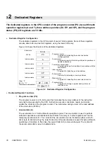
The condition code register (CCR) located in the lower 8 bits of the program status
(PS) consists of the C, V, Z, N, and H bits indicating the results of arithmetic
operations and the contents of transfer data, and the I, IL1, and IL0 bits for control
whether or not the CPU accepts interrupt requests.
n
Structure of Condition Code Register (CCR)
Figure 3.2.1a Structure of Condition Code Register
n
Arithmetic Operation Result Bits
l
Half-carry flag (H)
Set when a carry from bit 3 to bit 4 or a borrow from bit 4 to bit 3 occurs as a result of an
arithmetic operation. Cleared otherwise. As this flag is for the decimal adjustment instructions,
do not use this flag in cases other than addition or subtraction.
l
Negative flag (N)
Set if the most significant bit (MSB) is set to 1 as a result of an arithmetic operation. Cleared
when the bit is set to 0.
l
Zero flag (Z)
Set when an arithmetic operation results in 0. Cleared otherwise.
l
Overflow flag (V)
Set if the complement on 2 overflows as a result of an arithmetic operation. Reset if the overflow
does not occur.
l
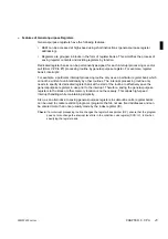
Carry flag (C)
Set when a carry from bit 7 or borrow to bit 7 occurs as a result of an arithmetic operation. Cleared
otherwise. Set to the shift-out value in case of a shift instruction.
Figure 3.2.1b shows the change of the carry flag by a shift instruction.
Figure 3.2.1b Change of Carry Flag by Shift Instruction
Half-carry flag
Interrupt enable flag
Interrupt level bits
Negative flag
Zero flag
Overflow flag
Carry flag
Bit 15 Bit 14 Bit 13 Bit 12 Bit 11 Bit 10 Bit 9 Bit 8 Bit 7 Bit 6 Bit 5 Bit 4 Bit 3 Bit 2 Bit 1 Bit 0
R4
R3
R2
R1
R0
—
—
—
H
I
IL1
IL0
N
Z
V
C
CCR initial value
X011XXXX
B
RP
CCR
PS
X: Indeterminate
C
Bit 7
Bit 0
Bit 7
Bit 0
• Left shift (ROLC)
• Right shift (RORC)
C
Summary of Contents for F2MC-8L MB89620 Series
Page 8: ......
Page 10: ...MB89620 series ...
Page 11: ...vi MB89620 series ...
Page 17: ...xii MB89620 series ...
Page 18: ...xvi MB89620 series ...
Page 30: ...MB89620 series CHAPTER 1 OVERVIEW 9 Memo ...
Page 34: ...MB89620 series CHAPTER 1 OVERVIEW 13 Memo ...
Page 42: ...MB89620 series CHAPTER 1 OVERVIEW 21 Memo ...
Page 49: ...28 CHAPTER 1 OVERVIEW MB89620 series ...
Page 62: ...MB89620 series CHAPTER 3 CPU 41 Memo ...
Page 78: ...MB89620 series CHAPTER 3 CPU 57 Memo ...
Page 82: ...MB89620 series CHAPTER 3 CPU 61 Memo ...
Page 86: ...MB89620 series CHAPTER 3 CPU 65 Memo ...
Page 90: ...MB89620 series CHAPTER 3 CPU 69 Memo ...
Page 96: ...MB89620 series CHAPTER 3 CPU 75 Memo ...
Page 122: ...MB89620 series CHAPTER 4 I O PORTS 101 Memo ...
Page 144: ...MB89620 series CHAPTER 5 TIMEBASE TIMER 123 Memo ...
Page 149: ...128 CHAPTER 5 TIMEBASE TIMER MB89620 series ...
Page 157: ...136 CHAPTER 6 WATCHDOG TIMER MB89620 series ...
Page 174: ...MB89620 series CHAPTER 7 8 BIT PWM TIMER 153 Memo ...
Page 177: ...156 CHAPTER 7 8 BIT PWM TIMER MB89620 series ...
Page 202: ...MB89620 series CHAPTER 9 16 BIT TIMER COUNTER 181 Memo ...
Page 217: ...196 CHAPTER 9 16 BIT TIMER COUNTER MB89620 series ...
Page 220: ...MB89620 series CHAPTER 10 8 BIT SERIAL I O SERIAL I O 1 AND SERIAL I O 2 199 Memo ...
Page 228: ...MB89620 series CHAPTER 10 8 BIT SERIAL I O SERIAL I O 1 AND SERIAL I O 2 207 Memo ...
Page 245: ...224 CHAPTER 10 8 BIT SERIAL I O SERIAL I O 1 AND SERIAL I O 2 MB89620 series ...
Page 266: ...MB89620 series CHAPTER 13 A D CONVERTER 245 13 Memo ...
Page 283: ...262 CHAPTER 13 A D CONVERTER MB89620 series ...
Page 289: ...268 CHAPTER 14 CLOCK MONITOR FUNCTION MB89620 series ...
Page 306: ...MB89620 series APPENDIX 285 APPEND Memo ...
Page 319: ...298 APPENDIX MB89620 series Memo ...
Page 321: ...2 ...
Page 354: ......


