5. Wiring design
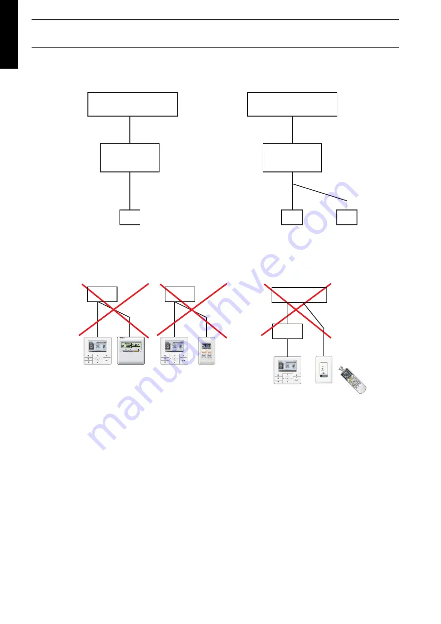
5-1. System diagram
A
Primary
Secon-
dary
B
C
Zone control
Interface
Indoor unit
Indoor unit
Remote controller
Remote controllers
1 remote controller
2 remote controllers
Zone control
Interface
A, B, and C: Remote controller cable.
Prohibited uses:
UTY-RVNYN AR-WAF**
AR-6TC**
AR-3TA**
(Accessory)
UTY-RVNYN UTY-RSNYN
SET TEMP.
START/STOP
Zone control interface
Zone control interface
UTY-RVNYN UTY-LRHYM
Zone control
interface
Indoor unit
*: Arbitrary character.
DESIGN & TECHNICAL MANUAL
- 10 -
ZONE CONTROL
SYSTEM


