background image

27

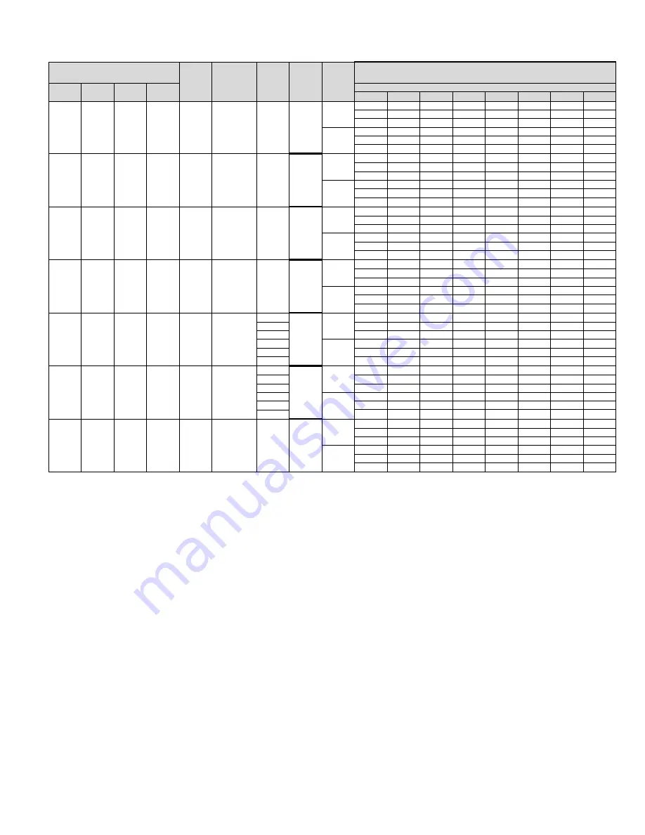
5.2 115/208/240/480V AIRFLOW PERFORMANCE DATA – SINGLE SPEED AIR HANDLER (CONSTANT TORQUE MOTOR)

Single Speed Air Handler

Blower Size/

Motor

Nonimal

Motor

Motor H

.

P

.

Speed

Width

Capacity

Type

Heat

# of Speeds

0

.

10 [

.

02]

0

.

20 [

.

0

5

]

0

.

30 [

.

07]

0

.4

0 [

.

10]

0

.5

0 [

.

12]

0

.

60 [

.

1

5

]

0

.

70 [

.

17]

10x8

CFM

837

713

608

554

485

1/3 [249]

RPM

565

587

630

692

751

5 Speed

Watts

95

81

88

74

66

CFM

683

615

572

RPM

789

842

892

Watts

140

159

155

10x8

CFM

814

692

589

535

467

1/3 [249]

RPM

592

613

656

719

778

5 Speed

Watts

108

90

97

82

73

CFM

808

629

584

RPM

789

842

892

Watts

148

168

163

10x8

CFM

902

846

788

742

679

1/3 [249]

RPM

596

645

694

741

791

5 Speed

Watts

105

108

116

121

130

CFM

858

816

770

RPM

834

879

925

Watts

185

182

214

10x8

CFM

882

827

769

723

661

1/3 [249]

RPM

595

670

719

767

817

5 Speed

Watts

113

125

124

129

197

CFM

833

791

746

RPM

852

898

944

Watts

192

189

222

935/1084 CFM

10x8

CFM

1093 [516]

1050 [496]

1017 [480]

977 [461]

935 [441]

[441/512 I/s]

1/2 [373]

RPM

671

725

764

809

852

5 Speed

Watts

153

168

174

180

188

CFM

1084 [512]

1040 [491]

1001 [472]

RPM

896

936

971

Watts

249

257

261

910/1059 CFM

10x8

CFM

1068 [504]

1025 [484]

992 [468]

952 [449]

910 [429]

[429/500 I/s]

1/2 [373]

RPM

711

765

804

849

892

5 Speed

Watts

164

179

185

191

199

CFM

1059 [500]

1015 [479]

976 [461]

RPM

936

976

1011

Watts

260

268

272

10x8

CFM

1270 [599]

1237 [584]

1199 [566]

1165 [550]

1130 [533]

1/2 [373]

RPM

775

816

846

882

926

5 Speed

Watts

237

249

259

268

277

CFM

1275 [602]

1244 [587]

1211 [571]

RPM

963

999

1029

Watts

338

348

363

No Heat

13kw Heater

No Heat

13kw heater

No Heat

18kw heater

No Heat

24

24

24

24

36

36

36

s

s

S

s

s

s

s

2.5

5

2

3

3

5

1130/1275 CFM 

[533/602 I/s]

4

5

2

5

683/485

4

5

2.5

5

2

3

1.5

5

683/485

2

3

2

5

858/697

4

5

Tonnage 

Application

Motor Speed From 

Factory

Manufacturer 

Recommended Air 

Flow Range (Min / 

Max) CFM

CFM[L/s] Air Delivery/RPM/Watts (No Filter)

External Static Pressure-Inches W

.

C

.

1.5

5

683/485

2

3

17

17

17

17

17

17

17

Summary of Contents for FH2417PTSJSN

Page 1: ...peration Failure to follow these instructions may result in improper installation adjustment service or maintenance possibly resulting in fire electrical shock property damage personal injury or death AIR HANDLERS FEATURING INDUSTRY STANDARD R 410A REFRIGERANT Single Speed High Efficiency with Aluminum Coil Two Speed High Efficiency 2 Stage with Aluminum Coil INSTALLATION INSTRUCTIONS r e f r i g ...

Page 2: ... 33 7 0 REFRIGERANT CONNECTIONS 33 7 1 1 TEV Sensing Bulb 33 7 1 2 Orifice Size 34 7 2 Electronic Expansion 34 7 3 EXV Vapor Line Thermister 35 7 4 Factory Programmed Superheat 36 7 5 Superheat Offset Dip Switch Settings 36 7 6 EXV Step Dip Switch 36 7 7 Diagnostics 37 7 8 EXV Standalone Control Physical Interface 37 7 9 EXV Standalone Control Optional Mounting Locations 37 7 10 EXV Standalone Wir...

Page 3: ...injury or death SEE SECTION 4 0 ELECTRICAL WIRING SEE SECTION 12 5 BLOWER ASSEMBLY REMOVAL REPLACEMENT WARNING Duct leaks can create an unbalanced system and draw pollutants such as dirt dust fumes and odors into the home causing property damage Fumes and odors from toxic volatile or flammable chemicals as well as automobile exhaust and carbon monoxide CO can be drawn into the living space through...

Page 4: ... coils or units containing evaporator coils that are located in any area of a structure where damage to the building or building contents may occur as a result of an overflow of the coil drain pan or a stoppage in the primary condensate drain piping See accessories for auxiliary horizontal overflow pan RXBM NOTICE When used in cooling applications excessive sweating may occur when unit is installe...

Page 5: ... unit warranty Duct leaks can create an unbalanced system and draw pollutants such as dirt dust fumes and odors into the home causing property damage Fumes and odors from toxic volatile or flammable chemicals as well as automobile exhaust and carbon monoxide CO can be drawn into the living space through leaking ducts and unbalanced duct systems causing personal injury or death see Figure 1 If air ...

Page 6: ...nit in accordance with any local code which may apply and the national codes Latest editions are available from National Fire Protection Association Inc Batterymarch Park Quincy MA 02269 These publications are ANSI NFPA No 70 Latest Edition National Electrical Code NFPA90A Installation of Air Conditioning and Ventilating Systems NFPA90B Installation of warm air heating and air conditioning systems...

Page 7: ...AGE A 115 1 60 D 480 3 60 J 208 240 1 60 NOMINAL CAPACITY 18 18 000 BTU H 42 42 000 BTU H 24 24 000 BTU H 48 48 000 BTU H 30 30 000 BTU H 60 60 000 BTU H 36 36 000 BTU H PRODUCT CATEGORY H AIR HANDLER TRADE BRAND F FUJITSU SPEED S SINGLE STAGE T TWO SPEED MOTOR TYPE P PSC T CONSTANT TORQUE METERING DEVICE T TEV WIDTH 17 17 5 600 1200 CFM 21 21 800 1600 CFM 24 24 5 1400 1800 CFM ...

Page 8: ...air han dler terminal block bring only two leads to the terminal block Cap insulate and fully secure the third lead The air handlers are shipped from the factory with the proper indoor coil installed and cannot be ordered without a coil The air handlers do not have an internal filter rack An external filter rack or other means of filtration is required 2 4A AVAILABLE MODELS FH6024TTSDSN FH3617TTSA...

Page 9: ...EAT IN mm ID MODEL NOMINAL CAPACITY EFFICIENCY METER EXV TXV PISTON LIQUID VAPOR REFRIGERANT CONNECTIONS SINGLE SPEED AIR HANDLER UNIT HEIGHT IN mm MOTOR TYPE 2 5A DIMENSIONAL DATA SINGLE SPEED MOTOR 17 24 T S T 3 8 9 53 3 4 19 05 421 2 1080 17 36 T S E 3 8 9 53 3 4 19 05 421 2 1080 17 36 T S T 3 8 9 53 3 4 19 05 421 2 1080 21 36 T H T 3 8 9 53 7 8 22 23 57 1448 21 36 T M T 3 8 9 53 7 8 22 23 501 ...

Page 10: ... breaker pair circuit at a time starting with the one on the right Loosen both lugs on the load side of the breaker Wires are bundles with wire ties one bundle going to the right lug and one bundle going to the left lug Using a screwdriver or pencil lift white plastic tab with hole away from breaker until breaker releases from mounting opening see Figure 5 With breaker held in hand rotate breaker ...

Page 11: ...w and horizontal right applica tion Remove the coil rail from the factory configuration 6 screws in all Fastener clear ance holes will need to be drilled in the cabinet sides proper hole locations are marked with dimples for this purpose Note that the shorter no notch coil rail must be mount ed on the left hand side to provide clearance for the drain pan condensate connection boss Reinstall the in...

Page 12: ...by removing the indoor coil and reinstalling 180 from original See Figure 5 3 3 INSTALLATION IN AN UNCONDITIONED SPACE The exterior cabinet of an air handler has a greater risk of sweating when installed in an unconditioned space than when it is installed in the conditioned space This is primarily DETAIL A ENSURE THE RETAIN ING CHANNEL IS FULLY ENGAGED WITH THE COIL RAIL RAILS RAILS ST A1213 02 ST...

Page 13: ...he insulation As required use a secondary pan that will protect the structure from excessive sweat ing or a restricted coil drain line If a heater kit is installed be sure the breaker or disconnect cover is sealed tightly to the door panel 3 4 INSTALLATION IN MOBILE MANUFACTURED HOMES 1 Air handler must be secured to the structure using L brackets or pipe strap 2 Allow a minimum of 24 inches 610 m...

Page 14: ...op Three 7 8 13 32 131 32 dia concentric knockouts are provided for connection of power wiring to unit Power wiring is connected to the power terminal block in unit control compartment 4 2 CONTROL WIRING IMPORTANT Class 2 low voltage control wire should not be run in conduit with power wiring and must be separated from power wiring unless class 1 wire of proper voltage rating is used Low voltage c...

Page 15: ...ield Installed Line Voltage WIRING INFORMATION Factory Standard B E Y R C R W1 C G Air Handler ODD R Y B W2 Y W BK G BK BL BR G Y W BL R Y W2 FIGURE 13 TYPICAL THERMOSTAT HEAT PUMP W ELECTRIC HEAT USING A HUMIDISTAT FOR DEHUMIDIFICATION C Y2 Heat Pump Thermostat Heat Pump Outdoor Unit D B G Field Installed Line Voltage WIRING INFORMATION Factory Standard B E Y R C R W1 C G Air Handler ODD R Y B W2...

Page 16: ... R W R BR PR C L FIGURE 18 2 STAGE THERMOSTAT HEAT PUMP ELECTRIC HEAT WITH HUMIDISTAT FOR DEHUMIDIFICATION Typical Two Stage Thermostat Heat Pump Outdoor Unit Field Installed Line Voltage WIRING INFORMATION Factory Standard W1 C G Air Handler Y2 ODD R Y1 B W2 E W1 C G Y2 R Y1 B W2 Y2 B D Y1 R BL Y Y BL R W R BR PR C L DHM FIGURE 17 2 STAGE THERMOSTAT HEAT PUMP ELECTRIC HEAT USING 2 STAGE THERMOSTA...

Page 17: ...R PR C L FIGURE 21 2 STAGE THERMOSTAT HEAT PUMP ELECTRIC HEAT WITH HUMIDISTAT FOR DEHUMIDIFICATION Typical Two Stage Thermostat Heat Pump Outdoor Unit Field Installed Line Voltage WIRING INFORMATION Factory Standard W1 C G Air Handler Y2 ODD R Y1 B W2 E W1 C G Y2 R Y1 B W2 Y2 B D Y1 R BL Y Y BL R W R BR PR C L DHM FIGURE 22 2 STAGE THERMOSTAT HEAT PUMP ELECTRIC HEAT USING 2 STAGE THERMOSTAT FOR DE...

Page 18: ...BR PR C L FIGURE 25 1 STAGE THERMOSTAT HEAT PUMP ELECTRIC HEAT WITH HUMIDISTAT FOR DEHUMIDIFICATION Typical Two Stage Thermostat Heat Pump Outdoor Unit Field Installed Line Voltage WIRING INFORMATION Factory Standard W1 C G Air Handler Y2 ODD R Y1 B W2 E W1 C G Y2 R Y1 B W2 Y2 B D Y1 R BL Y Y BL R W R BR PR C L DHM FIGURE 26 2 STAGE THERMOSTAT HEAT PUMP ELECTRIC HEAT USING 2 STAGE THERMOSTAT FOR D...

Page 19: ...ATING FOR MORE THAN 3 CONDUCTORS IN A RACEWAY OR CABLE SEE N E C FOR DERATING THE AMPACITY OF EACH CONDUCTOR 12 12 14 14 15 10 10 12 12 20 8 10 10 10 25 8 10 10 10 30 8 8 8 8 35 6 8 8 8 40 6 6 8 8 45 6 6 6 6 50 4 6 6 6 60 4 4 4 4 70 3 4 4 4 80 3 3 3 3 90 2 3 3 3 100 2 2 2 2 110 1 1 1 1 125 0 0 0 0 150 00 00 00 00 175 4 6 COPPER WIRE SIZE AWG 3 VOLTAGE DROP 200 61 150 46 100 30 50 15 WARNING The un...

Page 20: ... 34 6 40 0 0 44 50 45 50 RXBH 1724A18J 12 8 17 0 1 60 3 5 68 SINGLE 61 6 70 8 2 8 81 92 90 100 4 3 5 7 1 60 1 5 68 MULTIPLE CKT 1 20 5 23 6 2 8 29 33 30 35 8 5 11 3 1 60 2 5 68 MULTIPLE CKT 2 41 1 47 2 0 52 59 60 60 RXBH 1724A07C 5 4 7 2 3 60 3 2 4 SINGLE 15 0 17 3 2 8 23 26 25 30 RXBH 1724A10C 7 2 9 6 3 60 3 3 2 SINGLE 20 0 23 1 2 8 29 33 30 35 RXBH 1724A13C 9 4 12 5 3 60 3 4 17 SINGLE 26 1 30 1 ...

Page 21: ...6 4 0 SINGLE 50 0 57 8 4 68 77 70 80 RXBH 24A25C 9 0 12 0 3 60 3 4 0 MULTIPLE CKT 1 25 0 28 9 4 37 42 40 45 4 ton only 9 0 12 0 3 60 3 4 0 MULTIPLE CKT 2 25 0 28 9 0 32 37 35 40 RXBH 1724 07J 5 4 7 2 1 60 2 3 6 SINGLE 26 0 30 0 4 6 39 44 40 45 RXBH 1724 10J 7 2 9 6 1 60 2 4 8 SINGLE 34 6 40 0 4 6 49 56 50 60 RXBH 1724A15J 10 8 14 4 1 60 3 4 8 SINGLE 51 9 60 0 4 6 71 81 80 90 3 6 4 8 1 60 1 4 8 MUL...

Page 22: ...BJ A21 and RXBJ A31 can be used to convert multiple circuits to a single supply circuit Refer to Accessory Section for details HEATER HEATER NO TYPE SUPPLY CIRCUIT MOTOR MINIMUM MAXIMUM METER MODEL KW ELEMENTS KW PER CIRCUIT AMPS AMPACITY CIRCUIT CIRCUIT Nonimal EXV TXV NO 208 240V SINGLE CIRCUIT AMPACITY PROTECTION 480V MULTIPLE CIRCUIT 7 2 9 6 3 60 3 3 2 MULTIPLE CKT 1 20 0 23 1 4 6 31 35 35 35 ...

Page 23: ...35 RXBH 1724A13C 9 4 12 5 3 60 3 4 17 SINGLE 26 1 30 1 1 6 35 40 35 40 RXBH 1724 05J 3 6 4 8 1 60 1 4 8 SINGLE 17 3 20 0 3 8 27 30 30 30 RXBH 1724 07J 5 4 7 2 1 60 2 3 6 SINGLE 26 0 30 0 3 8 38 43 40 45 RXBH 1724 10J 7 2 9 6 1 60 2 4 8 SINGLE 34 6 40 0 3 8 48 55 50 60 RXBH 1724A15J 10 8 14 4 1 60 3 4 8 SINGLE 51 9 60 0 3 8 70 80 70 80 3 6 4 8 1 60 1 4 8 MULTIPLE CKT1 17 3 20 0 3 8 27 30 30 30 7 2 ...

Page 24: ... 14 4 19 2 3 3 2 SINGLE 40 0 46 2 4 6 56 64 60 70 7 2 9 6 3 3 2 MULTIPLE CKT 1 20 0 23 1 4 6 31 35 35 35 7 2 9 6 3 3 2 MULTIPLE CKT 2 20 0 23 1 0 25 29 25 30 RXBH 24A25C 18 0 24 0 6 4 0 SINGLE 50 0 57 8 4 6 69 78 70 80 9 0 12 0 3 4 0 MULTIPLE CKT 1 25 0 28 9 4 6 37 42 40 45 9 0 12 0 3 4 0 MULTIPLE CKT 2 25 0 28 9 0 32 37 35 40 RXBH 24A30C 21 6 28 8 6 4 8 SINGLE 60 0 69 4 4 6 81 93 90 100 RXBH 24A3...

Page 25: ...where the breakers apply has been UL approved for short circuit protection Ampacity not breaker size determines supply circuit wire size The ampacity listed on the unit rating plate and the Maximum and Minimum circuit breaker size noted above or in the units specification sheet or installation instructions provides the information to properly select wire and circuit breaker protector size The Nati...

Page 26: ...M 170 L s Ton Nominal Maximum kW Electric Heating 13 13 18 18 20 25 25 30 Minimum Electric Heat CFM L s 487 230 617 291 814 384 1054 497 1171 553 1502 709 1502 709 1666 786 Maximum Electric Heat Rise F C 80 26 7 63 17 2 66 18 9 51 10 6 49 9 4 50 10 50 10 54 12 2 5 0 AIRFLOW PERFORMANCE Airflow performance data is based on cooling performance with a coil and no filter in place Select performance ta...

Page 27: ...9 222 935 1084 CFM 10x8 CFM 1093 516 1050 496 1017 480 977 461 935 441 441 512 I s 1 2 373 RPM 671 725 764 809 852 5 Speed Watts 153 168 174 180 188 CFM 1084 512 1040 491 1001 472 RPM 896 936 971 Watts 249 257 261 910 1059 CFM 10x8 CFM 1068 504 1025 484 992 468 952 449 910 429 429 500 I s 1 2 373 RPM 711 765 804 849 892 5 Speed Watts 164 179 185 191 199 CFM 1059 500 1015 479 976 461 RPM 936 976 10...

Page 28: ...681 1401 661 1373 648 1337 631 3 4 559 RPM 781 825 867 905 949 5 Speed Watts 257 271 303 307 315 CFM 1447 683 1433 676 1402 662 RPM 987 1034 1065 Watts 394 406 405 10x10 CFM 1433 676 1402 662 1361 642 1333 629 1297 612 3 4 559 RPM 831 875 919 954 989 5 Speed Watts 277 295 313 319 325 CFM 1333 629 1300 613 1267 598 RPM 1011 1046 1080 Watts 350 364 377 10x10 CFM 1665 786 1631 770 1601 756 1572 742 1...

Page 29: ...M 1862 879 1822 860 1769 835 1741 822 1699 802 3 4 559 RPM 750 790 810 850 880 5 Speed Watts 410 420 430 455 479 CFM 1865 880 1826 862 1792 846 RPM 920 945 970 Watts 565 587 610 11x11 CFM 1705 805 1661 784 1632 770 1572 742 1517 716 3 4 559 RPM 663 701 741 782 819 5 Speed Watts 292 309 321 343 357 CFM 1697 801 1646 777 1601 756 RPM 857 895 920 Watts 447 466 473 11x11 CFM 1669 788 1625 767 1596 753...

Page 30: ...4 490 498 512 531 dual voltage CFM 1716 1669 1631 1594 1555 1522 1483 RPM 861 887 911 948 984 1015 1050 Watts 359 375 379 397 427 419 427 10x10 CFM 1817 1783 1748 1713 1679 1644 1609 3 4 Hp 559 RPM 915 947 979 1011 1043 1076 1108 2 Speed Watts 470 476 484 494 507 521 538 dual voltage CFM 1691 1653 1615 1577 1538 1500 1462 RPM 871 903 935 967 999 1031 1063 Watts 367 379 392 404 416 428 440 10x10 CF...

Page 31: ...54 907 990 1040 1065 1085 1117 Watts 197 209 221 233 745 257 269 281 293 305 CFM 889 727 566 404 RPM 592 609 660 716 Watts 88 84 80 76 CFM 1098 1037 977 916 855 794 734 673 RPM 669 716 753 829 909 946 970 1011 Watts 136 147 158 169 180 192 5 5 CFM 975 912 849 786 723 660 RPM 622 670 725 815 855 893 Watts 104 113 122 132 141 150 CFM 1298 1243 1188 1134 1079 1025 970 915 861 806 RPM 762 796 840 879 ...

Page 32: ...633 570 521 469 425 RPM 593 614 662 726 785 829 883 Watts 93 98 103 108 113 118 123 CFM 797 679 554 495 RPM 588 603 645 717 Watts 102 93 83 74 CFM 931 891 852 804 767 722 671 RPM 637 687 740 787 836 895 937 Watts 139 151 162 173 184 196 207 CFM 919 757 596 434 RPM 567 584 635 691 Watts 83 79 75 71 67 62 58 54 CFM 1128 1067 1007 946 885 824 764 703 RPM 644 691 728 804 884 921 945 986 Watts 131 142 ...

Page 33: ...rk to the unit flanges using proper fasteners for the type of duct used and tape the duct to unit joint as required to prevent air leaks 7 0 REFRIGERANT CONNECTIONS Keep the coil connections sealed until refrigerant connections are to be made See the Installation Instructions for the outdoor unit for details on line sizing tubing installation and charging information Coil is shipped with a low 5 1...

Page 34: ...eck piston installed The pis ton may need to be changed to a different orifice size depending upon the outdoor unit The table below lists the recommended orifice size for various outdoor units FIGURE 28 BULB LOCATION 10 O CLOCK 2 O CLOCK BULB VAPOR LINE BULB FIGURE 29 BULB LOCATION ...

Page 35: ... operate and maximize reverse refrigerant flow 7 3 EXV VAPOR LINE THERMISTER IMPORTANT DO NOT perform any brazing with the vapor line thermister attached to any line After brazing operations have been completed clamp the vapor line thermister securely on the vapor line at the 10 to 2 o clock position with the clip provided on the thermister Insulate the vapor line thermister and vapor line with th...

Page 36: ...the measurement of superheat by the air handler control For this reason the following dip switch settings have been provided to enable flexibility for various installation conditions 7 6 EXV STEP DIP SWITCH The EXV dip switch has an optional 500 or 1600 steps setting This dipswitch should currently be in the 500 step position only Rheem does not currently supply 1600 step EXV s The dipswitch makes...

Page 37: ...ing is factory installed inside the case on the tube sheet This location has been tested and approved for long term operation inside the highly humid environment In the event servicing the EXV control without opening the coil door or to see the operational lights while the system is in operation the following 37 O N 1 2 A 1 2 O N 1 2 O N 1 2 O N B C D FIGURE 32 EXV ENABLED COIL WIRING DIAGRAM 1 2 ...

Page 38: ...um tape over the screw holes in the tube sheet to prevent bypass air 7 10 EXV STANDALONE WIRING For proper operation the standalone EXV control requires 24VAC power and staged operation thermostat signals The following diagram should be used to connect the flying leads provided with the cased coil to the thermostat wiring When employed with the Econet Communicating System attach the flying leads p...

Page 39: ...R BR Y Y BL STATUS OPEN CLOSE SS SH1 SH2 R CY1Y2 EXV MOTOR SUCTION PRESSURE SUCTION TEMP COIL TEMP R BR Y Y BL GND T M SCHEMATIC DIAGRAM STATUS OPEN CLOSE SS SH1 SH2 90 101897 09 REV PART NO 00 WIRING INFORMATION WARNING CABINET MUST BE PERMANENTLY GROUNDED AND CONFORM TO I E C N E C C E C NATIONAL WIRING REGULATIONS AND LOCAL CODES AS APPLICABLE REPLACEMENT WIRE MUST BE THE SAME SIZE AND TYPE OF ...

Page 40: ... one filter loca tion For systems with a return air filter grill or multiple filter grills can have a filter installed at each of the return air openings If high efficiency filters or electronic air cleaners are used in the system it is important that the airflow is not reduced to maximize system performance and life Always verify that the system s airflow is not impaired by the filtering system t...

Page 41: ...r is not of concern during defrost the purple wire can be left disconnected Supplemental heat will then come on only when called for by second stage room thermostat 9 6 EMERGENCY HEAT HEATING HEAT PUMP If selector switch on thermostat is set to the emergency heat position the heat pump will be locked out of the heating circuit and all heating will be electric heat Jumper should be placed between W...

Page 42: ... 11 0 PRE START CHECKLIST PRE START CHECKLIST Is unit properly located level secure and service able Has auxiliary pan been provided under the unit with separate drain Units installed above a finished ceiling Is condensate line properly sized run trapped pitched and tested Is ductwork correctly sized run taped and insulat ed Have all cabinet openings and wiring been sealed with caulking Is the fil...

Page 43: ...ould become necessary to clean the blower motor and wheel If it becomes necessary to remove the blower assembly from the unit see instructions on removal and disassembly of motor blower and heater parts The blower motor and wheel may be cleaned by using a vacuum with a soft brush attachment Remove grease with a mild solvent such as hot water and detergent Be careful not to disturb the balance weig...

Page 44: ...ved the indoor blower motor can be removed and replaced using the following procedure Remove motor leads from the motor capacitor and blower relay Note lead locations for ease of reassembly Pull leads from plastic bushing in blower side Loosen the set screw holding blower wheel onto the motor shaft Shaft extends through blower hub so that a wrench can be used on the extended shaft to break the sha...

Page 45: ...are not limited to Circuit breakers heater controls heater limit controls heater elements motor motor capacitor blower relay control transformer blower wheel filter indoor coil and sheet metal parts When ordering replacement parts it is necessary to order by part number and include with the order the complete model number and serial number from the unit data plate See parts list for unit component...

Page 46: ...6 EXTERNAL FILTER BASE RXHF Nominal Cooling Auxiliary Horizontal Capacity Tons Overflow Pan Accessory Model Number 11 2 3 RXBM AC48 3621H 31 2 5 RXBM AC61 Coil Model Horizontal Adapter Kit Horizontal Adapter Kit Model Number Single Qty Model Number 10 pak Qty 2414 RXHH A01 RXHH A01x10 2417 RXHH A02 RXHH A02x10 3617 3621 RXHH A03 RXHH A03x10 4821 4824 RXHH A04 RXHH A04x10 6024 RXHH A05 RXHH A05x10 ...

Page 47: ...47 ...

Page 48: ...48 CM 0317 ...

Reviews: