●
IN-2
O
Offset setting.............................. 7-3, 7-10
Operation status.................................. 6-3
Operator panel .................................... 1-6
Option .......................................... 9-3, 9-4
P
Pad Assembly ..................................... 9-2
Paper
counter........................................... 6-2
weight ............................................ 5-3
Pick
roller............................................... 9-2
start time setting ..................... 7-3, 7-9
Plain paper.......................................... 5-3
Portrait ................................................ 9-6
Power
consumption ................................ 10-3
inlet ................................................ 1-4
switch............................................. 1-4
Precautions ......................................... 5-3
Previous button ................................... 1-7
R
Read Color........................................ 7-18
Reading
face ................................................ 9-5
mode.............................................. 9-5
Resetting abrasion counter .......... 7-3, 7-8
Resolution ........................................... 9-6
S
SCSI terminator setting..................... 7-13
Select
interface ....................................... 7-14
IPC mode..................................... 7-15
Setting
Display the TPS Board ID Number7-14
Grayscale Mode........................... 7-18
Ink Remain Counter..................... 7-19
Inprinter........................................ 7-20
IPC preset mode............................ 7-7
IPC Status Display....................... 7-12
low power mode .......................... 7-13
Multi feed detection
paper length ............................... 7-6
paper thickness.......................... 7-5
Numbering Print Function............ 7-20
Offset ........................................... 7-10
pick start time ................................ 7-9
SCSI terminator ........................... 7-13
time-out limit ................................ 7-10
Unicolor Reading ......................... 7-18
Setup mode ................................. 7-2, 7-3
Simplex ............................................... 9-5
Size..................................................... 9-6
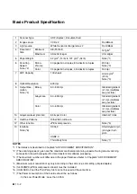
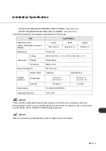
Specifications .......................... 10-2, 10-3
Start button .................................. 1-6, 1-7
Stop button .................................. 1-6, 1-7
T
Temporary error.................................. 6-4
Third party slot .................................... 1-4
Time-out limit setting ........................ 7-10
TPS board ID number display .......... 7-14
Turning
the power off.................................. 2-3
the power on.................................. 4-2
U
Unicolor Reading .............................. 7-18
Units ................................................... 1-3
Units and Assemblies ......................... 1-3
W
Weight .............................................. 10-3
Z
(Enter)button....................................... 1-7
(Exit)button ......................................... 1-7
(Left Arrow Key)button........................ 1-7
(Next)button ........................................ 1-7
Summary of Contents for fi-4340C
Page 1: ...fi 4340C Image Scanner Operator s Guide ...
Page 2: ......
Page 20: ......
Page 25: ... 1 5 Assemblies Guide A ASSY Pick roller Stacker Pad ASSY ...
Page 28: ... 1 8 ...
Page 58: ... 5 10 ...
Page 86: ... 7 22 ...
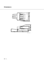
Page 104: ... 10 4 423 16 6 360 14 2 556 21 9 220 8 7 275 10 8 unit mm Dimensions ...
Page 110: ... GL 6 ...
Page 113: ... IN 3 Send To button 1 7 Start button 1 7 Stop button 1 7 ...

