1-2
Units and Assemblies
This section shows the exterior view and assemblies of the scanner. This section also provides the name
of each part and describes its functions.
Units
NOTICE
The shipping lock must be switched to the operating position before the scanner can be used. Refer to
page 2-4.
fi-4750L
Document holding pad
7
Document cover
8
ADF paper chute
3
ADF
1
Stacker
6
Power inlet
15
INT connector
11
Power switch
16
Document bed
9
Oparator panel
4
ADF
lever
5
Paper weight
(hidden)
2
IMP connector
10
Third party slot
12
Interface connector
13
EXT connector
14
Summary of Contents for fi-4750L
Page 1: ...Operator s Guide fi 4750L Image Scanner C150 E200 02EN ...
Page 2: ...fi 4750L Image Scanner Operator s Guide ...
Page 10: ...viii ...
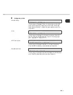
Page 23: ...1 11 Image transfer alarm Memory alarm EEPROM alarm FAN alarm IPC Board alarm ...
Page 24: ...1 12 ...
Page 44: ...3 10 ...
Page 57: ...5 3 unit mm Dimensions ...
Page 58: ...5 4 ...
Page 67: ...6 8 ...
Page 84: ...7 16 ...
Page 90: ...GL 6 ...
Page 93: ...DE 1 Declarations of Conformity ...
Page 94: ...DE 2 ...
Page 95: ......


