6-3
Video Interface Option
How to Install the Video Interface Option Board
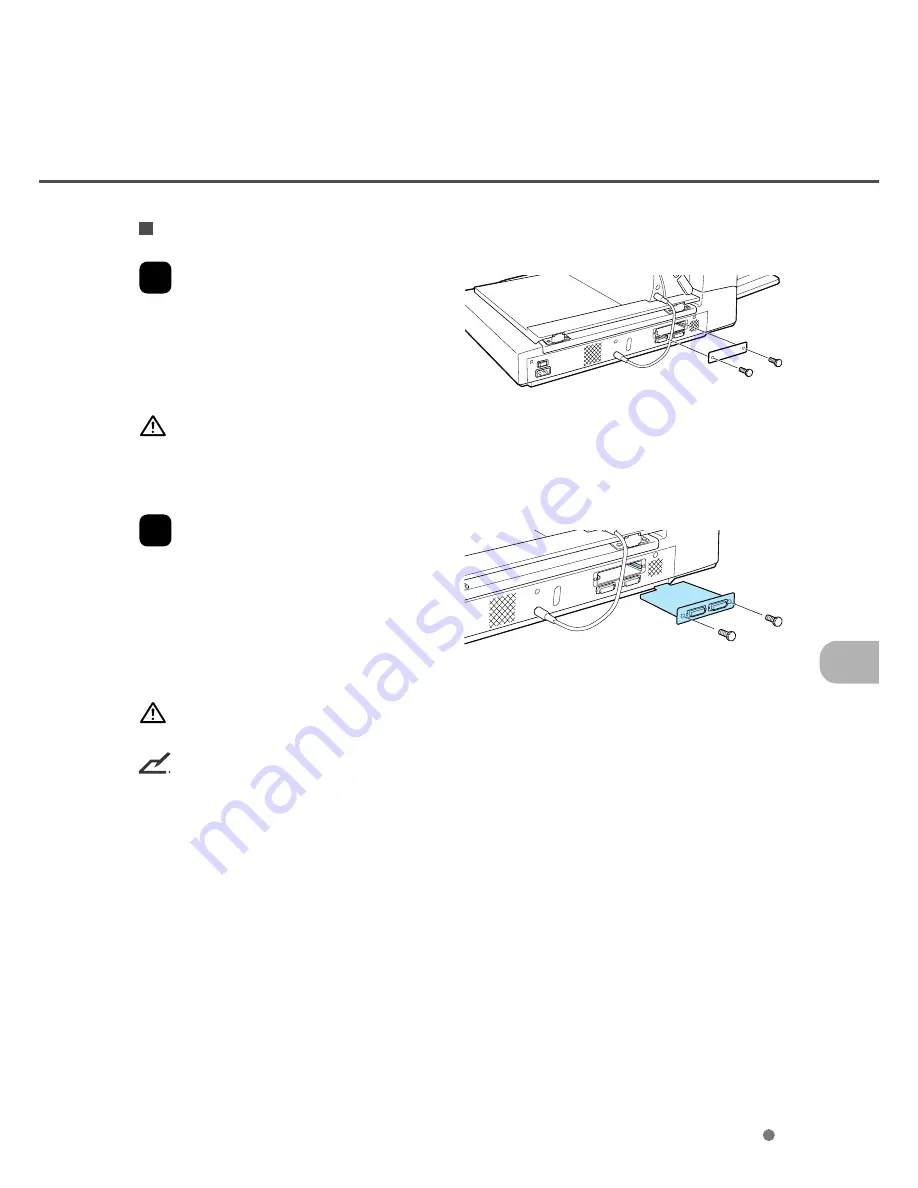
1
Loosen the two thumb screws to remove
the plate.
CAUTION
Turn Off the power before removing the Third Party slot plate.
2
Insert the board along the rails of the
third party slot. Make sure that the
connector is connected securely.
Secure the board with two thumb
screws.
WARNING
Protective measures are required to prevent damage from static electricity.
NOTICE
When the scanner power is turned On again, the scanner automatically recognizes the video interface
board.
Summary of Contents for fi-4750L
Page 1: ...Operator s Guide fi 4750L Image Scanner C150 E200 02EN ...
Page 2: ...fi 4750L Image Scanner Operator s Guide ...
Page 10: ...viii ...
Page 23: ...1 11 Image transfer alarm Memory alarm EEPROM alarm FAN alarm IPC Board alarm ...
Page 24: ...1 12 ...
Page 44: ...3 10 ...
Page 57: ...5 3 unit mm Dimensions ...
Page 58: ...5 4 ...
Page 67: ...6 8 ...
Page 84: ...7 16 ...
Page 90: ...GL 6 ...
Page 93: ...DE 1 Declarations of Conformity ...
Page 94: ...DE 2 ...
Page 95: ......


