CHAPTER 4
ETSI Configuration
Installing Cables
FNC-7500-0061-200
Issue 1, May 2009
FLASHWAVE 7500 Release 6.1
Equipment Installation
4-82
Fujitsu and Fujitsu Customer Use Only
4.16.6
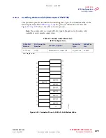
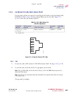
Installing LAN Cable (Optical/Tributary Shelf)
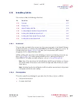
This procedure provides instructions for connecting to the LAN ports of the Optical and
Tributary shelves. LAN port connectors are located in the station interface area (SIA) at the
top front of the ETSI Optical/Tributary shelf (SHU4).
lists pertinent
information for these cables.
shows the cable connector pinouts.
Step
Task
1
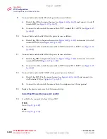
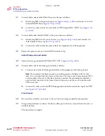
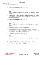
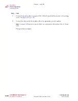
Connect the RJ-45 connector on one end of the LAN cable (21-332-xxx) to the primary
Tributary shelf or Auxiliary Optical shelf connector CN1.
Table 4-5: LAN Cable Information (ETSI Configuration)
Cable Part
Number
Connector Number
Cable
Description
Connector
Type
Cable Wire
Size
21-332-xxx
a
a
xxx = length in feet
For the Optical shelf:
CN2, CN6
LAN
connection
RJ-45
24 AWG
For Tributary shelves:
CN1, CN3
Figure 4-54: Connector Pinouts, LAN Cable
1
2
3
4
5
6
7
8
TXP
TXN
RXP
RXN
m1
71
4a
u_
1
Revision 1, June 2009
Summary of Contents for FLASHWAVE 7500
Page 8: ...Revision 1 June 2009 ...
Page 10: ...Revision 1 June 2009 ...
Page 16: ...Revision 1 June 2009 ...
Page 362: ...Revision 1 June 2009 ...
Page 386: ...Revision 1 June 2009 ...

