


91
CHAPTER 3 CPU AND CONTROL UNITS
- Operation initialization reset (RST) state
- Setting initialization reset (INIT) state
- Oscillation stabilization wait reset (RST) state
[Suspending the watchdog timer (deferring automatic generation)]
The watchdog timer initializes the watchdog reset generation flag to defer the generation of a watchdog
reset when the CPU is suspending program operation. Put briefly, the CPU suspends program operation
in the following states:
- Sleep state
- Stop state
- Oscillation stabilization wait RUN state
- During DMA transfer to the D-bus (data bus)
- During a break when the emulator debugger is being used
Note that, when the timebase counter is cleared, the watchdog reset generation flag is also initialized at
the same time, deferring the generation of a watchdog reset.
●
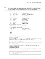
Timebase timer
The timebase timer generates an interval interrupt using the timebase counter output. This timer is
suitable for applications which involve time measurement for relatively long time up to {base clock
signal × 2
27
} cycles, such as the main PLL lock wait time or subclock oscillation stabilization wait
time.
The timebase timer generates a timebase timer interrupt request upon detection of that falling edge of
the timebase counter output which corresponds to the set interval.
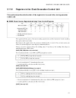
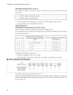
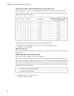
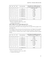
[Activating the timebase timer and setting its time interval]
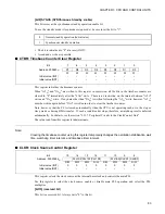
The time interval for the timebase timer is set by the TBC2, TBC1, and TBC0 bits (bit13 to bit11) in the
TBCR (timebase counter control register).
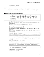
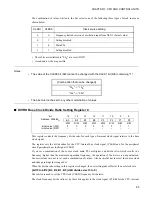
Since that falling edge of the timebase counter output which corresponds to the set interval is always
detected, clear the TBIF bit (bit15) first after setting the time interval and then set the TBIE bit (bit14)
to "1" to enable the interrupt request output.
Before changing the time interval, set the TBIE bit (bit14) to "0" to disable the interrupt request output.
The timebase counter keeps counting without being affected by these settings. To obtain the accurate
interval interrupt time, therefore, clear the timebase counter before enabling interrupts. Otherwise, an
interrupt request may occur immediately after interrupts are enabled.
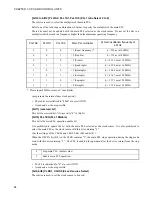
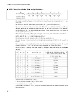
[Clearing the timebase counter using a program]
When "A5
H
" and "5A
H
" are written, in this order, to the CTBR (timebase counter clear register), all the
bits in the timebase counter are cleared to "0" immediately after the "5A
H
" write. There is no restriction
on the interval between "A5
H
" write and "5A
H
" write. If any data other than "5A
H
" is written following
the "A5
H
" write, however, "A5
H
" must be written again before "5A
H
" is written in order to clear the
timebase counter.
When the timebase counter is cleared in this way, the watchdog reset generation flag is initialized at the
same time, temporarily deferring the generation of a watchdog reset.
Summary of Contents for FR60Lite
Page 3: ......
Page 5: ......
Page 115: ...100 CHAPTER 3 CPU AND CONTROL UNITS ...
Page 127: ...112 CHAPTER 4 I O PORTS ...
Page 143: ...128 CHAPTER 5 INTERRUPT CONTROLLER ...
Page 155: ...140 CHAPTER 6 EXTERNAL INTERRUPT AND NMI CONTROLLER ...
Page 197: ...182 CHAPTER 9 PPG Programmable Pulse Generator ...
Page 337: ...322 CHAPTER 13 UART ...
Page 417: ...402 CHAPTER 16 DMAC DMA Controller ...
Page 445: ...430 CHAPTER 17 FLASH MEMORY ...
Page 451: ...436 CHAPTER 18 SERIAL PROGRAMMING CONNECTION ...
Page 493: ...478 APPENDIX F Precautions on Handling ...
Page 494: ...479 INDEX INDEX The index follows on the next page This is listed in alphabetic order ...
Page 507: ...492 INDEX ...
Page 509: ......


