


118
CHAPTER 5 INTERRUPT CONTROLLER
5.2
Interrupt Control Registers
This section describes register configuration and functions of interrupt controller.
■
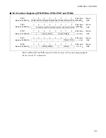
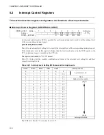
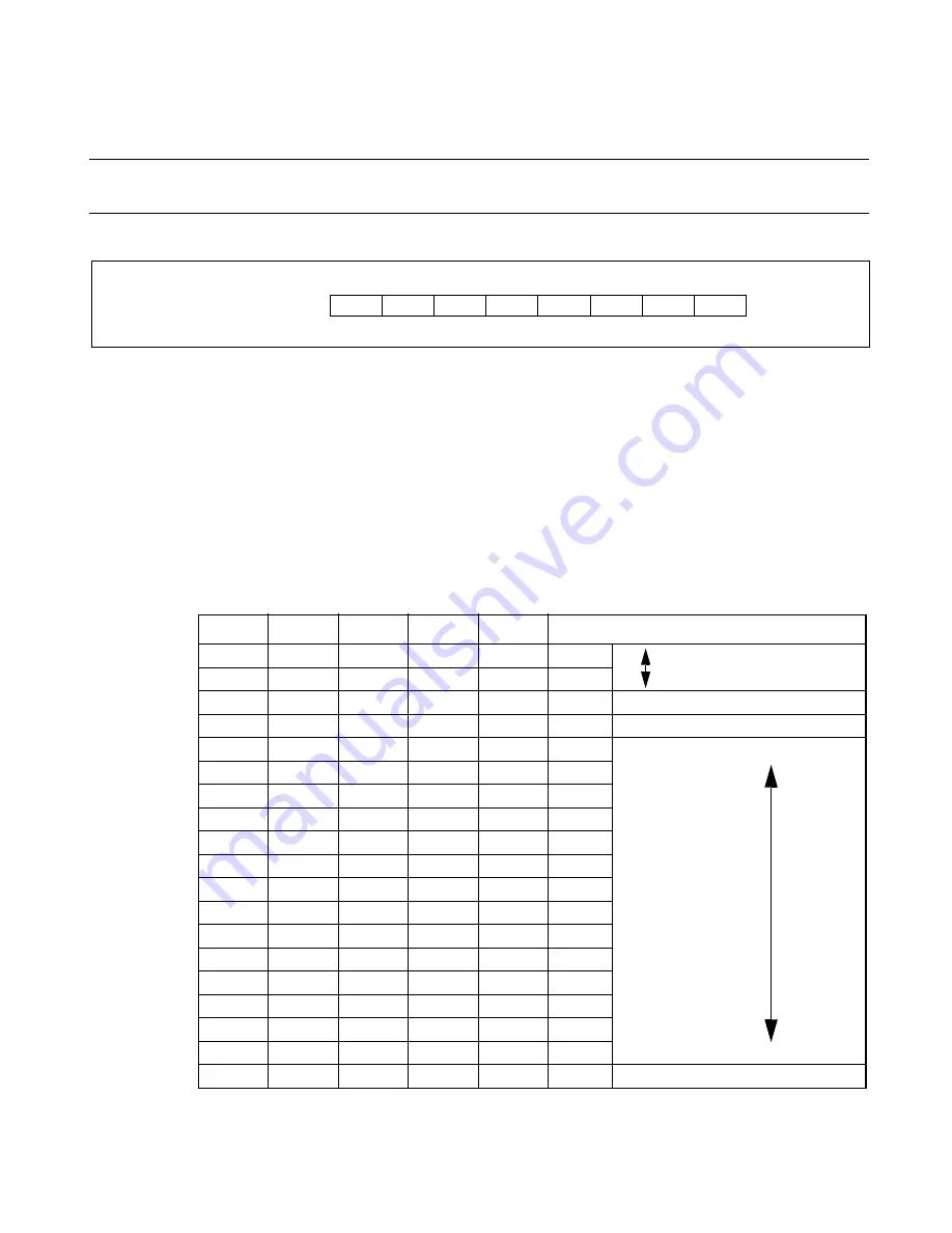
Interrupt Control Register (ICR:ICR00 to ICR47)
An interrupt control register (ICR) is provided for each interrupt input and is used to set the interrupt level
of the corresponding interrupt request.
[bit4 to bit0] ICR4 to ICR0
These bits are interrupt level setting bits to specify the interrupt level of the corresponding interrupt request.
If the interrupt level set in this register is higher than the level mask value set in the ILM register in the
CPU, an interrupt request is masked on the CPU side.
The register is initialized to "11111
B
" at reset.
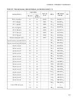
Table 5.2-1 below lists the available combinations of values of the interrupt level setting bits and their
respective interrupt levels.
The ICR4 bit is fixed at "1"; it cannot be set to "0".
ICR00 to ICR47 Bit No.
→
7
6
5
4
3
2
1
0
Initial value
Address
–
–
–
ICR4
ICR3
ICR2
ICR1
ICR0
---11111
B
000440
H
to 00046F
H
R
R/W
R/W
R/W
R/W
Table 5.2-1 Interrupt Level Setting Bit Values and Interrupt Levels
ICR4
ICR3
ICR2
ICR1
ICR0
Interrupt Level
0
0
0
0
0
0
System-reserved
0
1
1
1
0
14
0
1
1
1
1
15
NMI
1
0
0
0
0
16
Highest level available
1
0
0
0
1
17
(High)
1
0
0
1
0
18
1
0
0
1
1
19
1
0
1
0
0
20
1
0
1
0
1
21
1
0
1
1
0
22
1
0
1
1
1
23
1
1
0
0
0
24
1
1
0
0
1
25
1
1
0
1
0
26
1
1
0
1
1
27
1
1
1
0
0
28
1
1
1
0
1
29
1
1
1
1
0
30
(Low)
1
1
1
1
1
31
Interrupt-disabled
Summary of Contents for FR60Lite
Page 3: ......
Page 5: ......
Page 115: ...100 CHAPTER 3 CPU AND CONTROL UNITS ...
Page 127: ...112 CHAPTER 4 I O PORTS ...
Page 143: ...128 CHAPTER 5 INTERRUPT CONTROLLER ...
Page 155: ...140 CHAPTER 6 EXTERNAL INTERRUPT AND NMI CONTROLLER ...
Page 197: ...182 CHAPTER 9 PPG Programmable Pulse Generator ...
Page 337: ...322 CHAPTER 13 UART ...
Page 417: ...402 CHAPTER 16 DMAC DMA Controller ...
Page 445: ...430 CHAPTER 17 FLASH MEMORY ...
Page 451: ...436 CHAPTER 18 SERIAL PROGRAMMING CONNECTION ...
Page 493: ...478 APPENDIX F Precautions on Handling ...
Page 494: ...479 INDEX INDEX The index follows on the next page This is listed in alphabetic order ...
Page 507: ...492 INDEX ...
Page 509: ......


