


ix
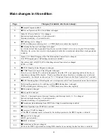
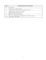
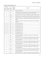
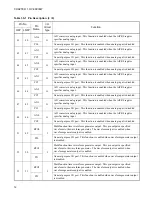
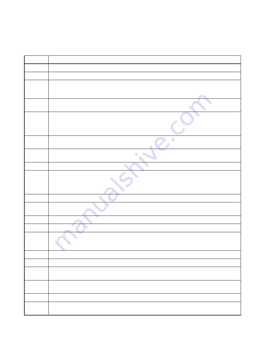
Main changes in this edition
Page
Changes (For details, refer to main body.)
i
■
Sample Program is added.
23
●
Note on Operation in PLL Clock Mode is changed.
53
Table 3.8-3 Vector Table (1 / 3) is changed.
(Instruction break exception
→
System-reserved)
(Operand break trap
→
System-reserved)
66
●
Watchdog reset is changed.
(WPR (watchdog reset defer register)
→
CTBR (timebase counter clear register))
70
■
Selecting the Source Clock Signal is changed.
(
φ
is the base clock that is generated from the source clock divided by two or by using the PLL oscillation.
Therefore, the system base clock is a clock generated in the above-mentioned internal base clock generation.
is added.)
76
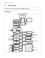
Figure 3.11-1 Block Diagram of the Clock Generation Control Unit is changed.
(The WPR register part of [Watchdog controller] is deleted.)
78
The table in [bit9, bit8] WT1,WT0 (Watchdog interval Time select) is changed.
(WPR
→
CTBR)
78
■
STCR: Standby Control Register is changed.
83
■
CTBR: Timebase Counter Clear Register is changed.
(Note, however, that the FF is cleared automatically when the CPU is not operating such as in the stop or
sleep mode or during DMA transfer. If such a condition develops, therefore, a watchdog reset is deferred
automatically. For details, see the section "3.11.7 Peripheral Circuits in the Clock Control Unit". is added.)
85
■
WPR: Watchdog Reset Defer Register in 3.11.6 Registers in the Clock Generation Control Unit is deleted.
90
[Deferring the generation of a watchdog reset] in
●
Watchdog timer is changed.
(WPR (watchdog reset defer register)
→
CTBR (timebase counter clear register))
96
●
Sleep mode is changed.
97
●
Stop mode is changed.
121
Table 5.3-1 Interrupt Sources, Interrupt Numbers, and Interrupt Levels (1 / 3) is changed.
(Instruction break exception
→
System-reserved)
(Operand break trap
→
System-reserved)
137
■
Precautions when Returning from STOP State Using External Interrupt is added.
138
■
Return Operation from STOP State is added.
304
■
Features of UART is changed.
(
•
The DMAC interrupt source is cleared by the writing operation to the DRCL register. is deleted.)
305
■
Register List is changed.
(DRCL part is deleted.)
312
■
DRCL is deleted.
318
■
Precautions on Usage is changed.
(Write to the DRCL register before starting DMA transfer by an interrupt for the first time. is deleted.)
Summary of Contents for FR60Lite
Page 3: ......
Page 5: ......
Page 115: ...100 CHAPTER 3 CPU AND CONTROL UNITS ...
Page 127: ...112 CHAPTER 4 I O PORTS ...
Page 143: ...128 CHAPTER 5 INTERRUPT CONTROLLER ...
Page 155: ...140 CHAPTER 6 EXTERNAL INTERRUPT AND NMI CONTROLLER ...
Page 197: ...182 CHAPTER 9 PPG Programmable Pulse Generator ...
Page 337: ...322 CHAPTER 13 UART ...
Page 417: ...402 CHAPTER 16 DMAC DMA Controller ...
Page 445: ...430 CHAPTER 17 FLASH MEMORY ...
Page 451: ...436 CHAPTER 18 SERIAL PROGRAMMING CONNECTION ...
Page 493: ...478 APPENDIX F Precautions on Handling ...
Page 494: ...479 INDEX INDEX The index follows on the next page This is listed in alphabetic order ...
Page 507: ...492 INDEX ...
Page 509: ......


