


126
CHAPTER 5 INTERRUPT CONTROLLER
●
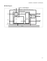
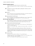
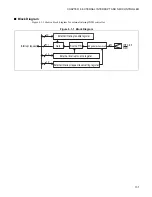
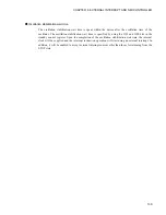
Hardware configuration
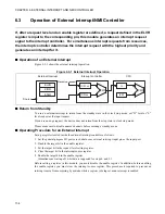
The flow of each signal is illustrated below.
Figure 5.3-1 Flow of Each Signal
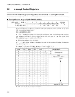
●
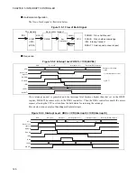
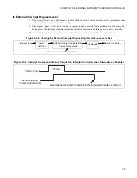
Sequence
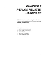
Figure 5.3-2 Interrupt Level: HRCL < ICR (LEVEL)
If an interrupt request is generated and the interrupt level becomes higher than that set in the HRCL
register, MHALTI becomes active to the DMA controller. Then the DMA controller cancels the access
request, allowing the CPU to return from the hold status for servicing the interrupt.
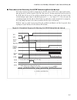
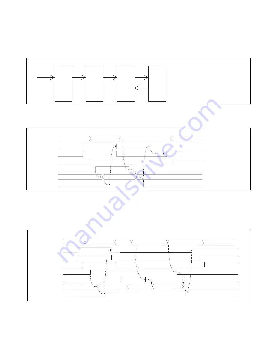
Given below is an example of handling multiple interrupts.
Figure 5.3-3 Interrupt Level: HRCL < ICR (Interrupt I) < ICR (Interrupt II)
This module
Bus access request
IRQ
MHALTI
DHREQ
DHREQ: D-bus hold request
I-UNIT
DMAC
Bus
Converter
CPU
DHACK: D-bus hold acknowledge
(ICR)
IRQ: Interrupt request
(HRCL)
DHACK
MHALTI: Hold request cancel request
MHALTI
LEVEL
IRQ
DHACK
DHREQ
Bus access
request
CPU
Bus hold
RUN
Example of interrupt
routine
2) RETI
|
1) Interrupt request clear
Bus hold (DMA transfer)
Interrupt service
1)
2)
MHALTI
LEVEL
IRQ2
DHACK
DHREQ
CPU
Bus hold
RUN
3)
IRQ1
Interrupt I
Interrupt service II
Interrupt service I
Bus hold (DMA transfer)
Bus access
request
4) 1) 2)
Summary of Contents for FR60Lite
Page 3: ......
Page 5: ......
Page 115: ...100 CHAPTER 3 CPU AND CONTROL UNITS ...
Page 127: ...112 CHAPTER 4 I O PORTS ...
Page 143: ...128 CHAPTER 5 INTERRUPT CONTROLLER ...
Page 155: ...140 CHAPTER 6 EXTERNAL INTERRUPT AND NMI CONTROLLER ...
Page 197: ...182 CHAPTER 9 PPG Programmable Pulse Generator ...
Page 337: ...322 CHAPTER 13 UART ...
Page 417: ...402 CHAPTER 16 DMAC DMA Controller ...
Page 445: ...430 CHAPTER 17 FLASH MEMORY ...
Page 451: ...436 CHAPTER 18 SERIAL PROGRAMMING CONNECTION ...
Page 493: ...478 APPENDIX F Precautions on Handling ...
Page 494: ...479 INDEX INDEX The index follows on the next page This is listed in alphabetic order ...
Page 507: ...492 INDEX ...
Page 509: ......


