


172
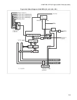
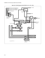
CHAPTER 9 PPG (Programmable Pulse Generator)
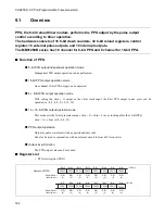
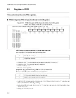
9.3
Register of PPG
This section describes the PPG registers.
■
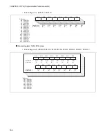
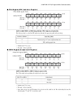
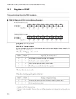
PPGCn Register (PPGn Operation Mode Control Register)
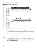
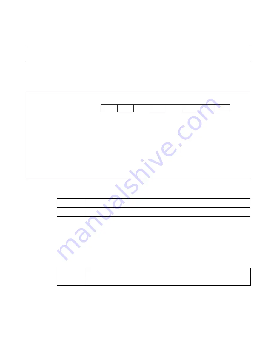
Figure 9.3-1 PPGCn Register (PPGn Operation Mode Control Register)
n=0, 1, 2, 3, 4, 5, 6, 7, 8, 9, 10, 11, 12, 13, 14, 15
[bit7] PIEn (Ppg Interrupt Enable): PPG interrupt enable bit
This bit controls a PPG interrupt enable as described below.
•
If this bit is set to "1", an interrupt request is generated when the PUFn is set to "1".
•
If this bit is set to "0", no interrupt request is generated.
•
Initialized to "0" by reset.
•
The read / write is possible.
[bit6] PUFn (Ppg Underflow Flag): PPG counter underflow bit
This bit controls PPG counter underflow bit as described below.
•
In the 8-bit PPG 2ch mode and the 8-bit pre 8-bit PPG mode, this bit is set to "1" when the count
value of ch0 underflows from "00
H
" to "FF
H
".
•
In the 16-bit PPG 1ch mode, this bit is set to "1" when the count value of ch1/ch0 underflows from
"0000
H
" to "FFFF
H
".
•
Writing "0" clears the bit to "0".
Read/Write
→
Initial value
→
PPGC0 to PPGC15 operation mode control register (PPGCn)
n = 0 to 15
Address:
ch
:000108
H
ch
:000109
H
ch
:00010A
H
ch
:00010B
H
ch
:000114
H
ch
:000115
H
ch
:000116
H
ch
:000117
H
ch
:000120
H
ch
0
1
2
3
4
5
6
7
8
9 :000121
H
ch10 :000122
H
ch11 :000123
H
ch12 :00012C
H
ch13 :00012D
H
ch14 :00012E
H
ch15 :00012F
H
R/W
(0)
R/W
(0)
R/W
(0)
R/W
(0)
R/W
(0)
R/W
(0)
R/W
(0)
-
(X)
Bit7
Bit6
Bit5
Bit4
Bit3
Bit2
Bit1
Bit0
PIEn
PUFn
INTMn
PCS1
PCS0
MD1
MD0
-
0
Disables the interrupt.
1
Enables the interrupt.
0
PPG counter underflow has not been detected.
1
PPG counter underflow has been detected.
Summary of Contents for FR60Lite
Page 3: ......
Page 5: ......
Page 115: ...100 CHAPTER 3 CPU AND CONTROL UNITS ...
Page 127: ...112 CHAPTER 4 I O PORTS ...
Page 143: ...128 CHAPTER 5 INTERRUPT CONTROLLER ...
Page 155: ...140 CHAPTER 6 EXTERNAL INTERRUPT AND NMI CONTROLLER ...
Page 197: ...182 CHAPTER 9 PPG Programmable Pulse Generator ...
Page 337: ...322 CHAPTER 13 UART ...
Page 417: ...402 CHAPTER 16 DMAC DMA Controller ...
Page 445: ...430 CHAPTER 17 FLASH MEMORY ...
Page 451: ...436 CHAPTER 18 SERIAL PROGRAMMING CONNECTION ...
Page 493: ...478 APPENDIX F Precautions on Handling ...
Page 494: ...479 INDEX INDEX The index follows on the next page This is listed in alphabetic order ...
Page 507: ...492 INDEX ...
Page 509: ......


