


178
CHAPTER 9 PPG (Programmable Pulse Generator)
■
PPG Output Operation
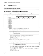
PPG activates this block and starts counting when the bits of each channel on the TRG register (PPG
activation register) are set to "1". After operation starts, the count operation is stopped when each channel
bit of TRG register is set to "0". After having stopped, the pulse output holds "L" level.
Do not set the PPG channel as the operating state, with the prescaler channel as the stopped state, in the 8-
bit pre 8-bit PPG mode and the 16-bit pre 16-bit PPG mode.
In the 16-bit PPG mode, control the start and stop for PENn of each channel on TRG register
simultaneously (n = 0 to 15).
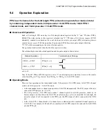
PPG output operation is explained below.
In PPG operation, the pulse wave with any frequency/duty ratio (the ratio between "H" level period and "L"
level period in pulse wave) is outputted continuously. If the pulse wave output is started, PPG will not stop
it before operation stop is set.
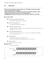
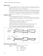
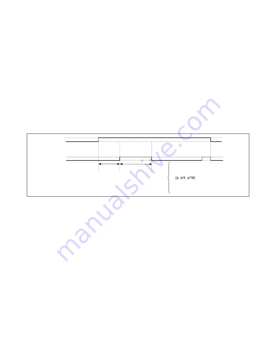
Figure 9.4-1 shows the output waveform of PPG operation.
Figure 9.4-1 Output Waveform of PPG Output Operation
■
Relation between Reload Value and Pulse Width
The pulse width to be outputted is the value that multiplies the cycle of the count clock by the value in the
reload register plus 1. Note that the pulse width will be one cycle of the count clock when the reload
register value is set to "00
H
" at operating the 8-bit PPG and when the reload register value is set to "0000
H
"
at operating the 16-bit PPG. Furthermore, the pulse width will be 256 cycles of the count clock when the
reload register value is set to "FF
H
" at operating the 8-bit PPG and will be 65536 cycles of the count clock
when the reload register value is set to "FFFF
H
" at operating the 16-bit PPG.
The equations for calculating the pulse width are shown below:
Output pin
PPG
T
×
(L+1)
PENn
Start operation
by PENn
(from “L” side)
Start
L: PRLL value
H: PRLH value
T: Machine clock
or
Input from timebase counter
(by clock select of PPGC)
T
×
(H+1)
n = 0 to 15
L: PRLL value
H: PRLH value
T: input clock cycle
Ph: high pulse width
Pl: low pulse width
Pl = T
×
(L + 1)
Ph = T
×
(H + 1)
{
Summary of Contents for FR60Lite
Page 3: ......
Page 5: ......
Page 115: ...100 CHAPTER 3 CPU AND CONTROL UNITS ...
Page 127: ...112 CHAPTER 4 I O PORTS ...
Page 143: ...128 CHAPTER 5 INTERRUPT CONTROLLER ...
Page 155: ...140 CHAPTER 6 EXTERNAL INTERRUPT AND NMI CONTROLLER ...
Page 197: ...182 CHAPTER 9 PPG Programmable Pulse Generator ...
Page 337: ...322 CHAPTER 13 UART ...
Page 417: ...402 CHAPTER 16 DMAC DMA Controller ...
Page 445: ...430 CHAPTER 17 FLASH MEMORY ...
Page 451: ...436 CHAPTER 18 SERIAL PROGRAMMING CONNECTION ...
Page 493: ...478 APPENDIX F Precautions on Handling ...
Page 494: ...479 INDEX INDEX The index follows on the next page This is listed in alphabetic order ...
Page 507: ...492 INDEX ...
Page 509: ......


