


188
CHAPTER 10 PWC (Pulse Width Count: Pulse Width Measurement)
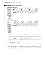
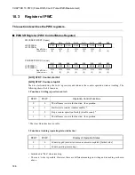
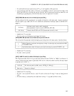
[bit10] OVIE: Counter overflow interrupt request enable bit
This bit controls a counter overflow interrupt request as described below.
•
Initialized to "0" when resetting.
•
The read / write is possible.
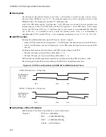
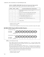
[bit9] ERR: Error flag
The flag indicates that the next measuring is completed before reading the measurement result in PWCR0
or PWCR1 in the continuous measurement mode of the pulse width count mode. At this point, the PWCR0
or PWCR1is updated to a new measurement result, the previous measurement result will be lost. The
measurement is continued regardless of this bit value.
•
Initialized to "0" at resetting.
•
This bit is read-only. Writing does not change the bit value.
[bit8] (Reserved)
Reserved bit.
Read value is "0".
Be sure to write "0".
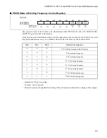
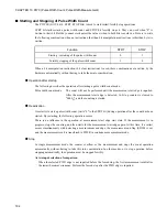
[bit7, bit6] CKS1, CKS0: Clock selection bits
Select an internal counter as listed in the table below.
•
Initialized to "00
B
" at resetting.
•
The read / write is possible. Do not set "11
B
".
•
These bits must not be updated after starting. These bits must be written before starting or after stopped.
0
Disable the overflow interrupt request output (an interrupt not generated when OVIR is set)
[Initial value]
1
Enable overflow interrupt request output (interrupt is generated when OVIR is set)
Set factor
Set when the measurement result has not been read is lost because of the next result.
Clear factor
Cleared when PWCR0 or PWCR1 (measurement result) is read.
CKS1
CKS0
Count Clock Selection
0
0
Clock generated by dividing the machine clock by 4 [Initial value]
0
1
Clock generated by dividing the machine clock by 16
1
0
Clock generated by dividing the machine clock by 32
1
1
Setting disabled
Summary of Contents for FR60Lite
Page 3: ......
Page 5: ......
Page 115: ...100 CHAPTER 3 CPU AND CONTROL UNITS ...
Page 127: ...112 CHAPTER 4 I O PORTS ...
Page 143: ...128 CHAPTER 5 INTERRUPT CONTROLLER ...
Page 155: ...140 CHAPTER 6 EXTERNAL INTERRUPT AND NMI CONTROLLER ...
Page 197: ...182 CHAPTER 9 PPG Programmable Pulse Generator ...
Page 337: ...322 CHAPTER 13 UART ...
Page 417: ...402 CHAPTER 16 DMAC DMA Controller ...
Page 445: ...430 CHAPTER 17 FLASH MEMORY ...
Page 451: ...436 CHAPTER 18 SERIAL PROGRAMMING CONNECTION ...
Page 493: ...478 APPENDIX F Precautions on Handling ...
Page 494: ...479 INDEX INDEX The index follows on the next page This is listed in alphabetic order ...
Page 507: ...492 INDEX ...
Page 509: ......


