


10
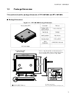
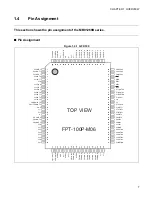
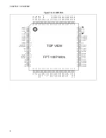
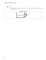
CHAPTER 1 OVERVIEW
9
7
TIN2
C
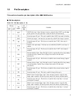
Reload timer 2 external trigger input. Since this input is used as required when
trigger input is enabled, the port output must remain off unless used intentionally.
P53
General-purpose I/O port. This function is enabled when reload timer 2 external
clock input is disabled.
10
8
INT0
E
External interrupt input. Since this input is used as required when the corresponding
external interrupt is enabled, the port output must remain off unless used
intentionally.
P54
General-purpose I/O port. This function is enabled when external interrupt input is
disabled.
11
9
INT1
E
External interrupt input. Since this input is used as required when the corresponding
external interrupt is enabled, the port output must remain off unless used
intentionally.
P55
General-purpose I/O port. This function is enabled when external interrupt input is
disabled.
12
10
INT2
E
External interrupt input. Since this input is used as required when the corresponding
external interrupt is enabled, the port output must remain off unless used
intentionally.
P56
General-purpose I/O port. This function is enabled when external interrupt input is
disabled.
13
11
INT3
E
External interrupt input. Since this input is used as required when the corresponding
external interrupt is enabled, the port output must remain off unless used
intentionally.
P57
General-purpose I/O port. This function is enabled when external interrupt input is
disabled.
14
12
CKI
E
Free-running timer external clock input pin. Since this input is used as required
when selected as the external clock input for the free-running timer, the port output
must remain off unless used intentionally.
INT4
External interrupt input. Since this input is used as required when the corresponding
external interrupt is enabled, the port output must remain off unless used
intentionally.
PG0
General-purpose I/O port. This port is enabled when free-running timer external
clock input and external interrupt input are disabled.
15
13
PPG0
E
PPG timer 0 output. This function is enabled when PPG timer 0 output is enabled.
INT5
External interrupt input. Since this input is used as required when the corresponding
external interrupt is enabled, the port output must remain off unless used
intentionally.
PG1
General-purpose I/O port. This port is enabled when PPG timer 0 output and
external interrupt input are disabled.
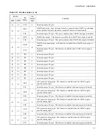
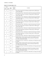
Table 1.5-1 Pin Description (2 / 9)
Pin No.
Pin
Name
I/O
Circuit
Type
Function
QFP
LQFP
Summary of Contents for FR60Lite
Page 3: ......
Page 5: ......
Page 115: ...100 CHAPTER 3 CPU AND CONTROL UNITS ...
Page 127: ...112 CHAPTER 4 I O PORTS ...
Page 143: ...128 CHAPTER 5 INTERRUPT CONTROLLER ...
Page 155: ...140 CHAPTER 6 EXTERNAL INTERRUPT AND NMI CONTROLLER ...
Page 197: ...182 CHAPTER 9 PPG Programmable Pulse Generator ...
Page 337: ...322 CHAPTER 13 UART ...
Page 417: ...402 CHAPTER 16 DMAC DMA Controller ...
Page 445: ...430 CHAPTER 17 FLASH MEMORY ...
Page 451: ...436 CHAPTER 18 SERIAL PROGRAMMING CONNECTION ...
Page 493: ...478 APPENDIX F Precautions on Handling ...
Page 494: ...479 INDEX INDEX The index follows on the next page This is listed in alphabetic order ...
Page 507: ...492 INDEX ...
Page 509: ......


