


240
CHAPTER 11 MULTIFUNCTIONAL TIMER
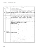
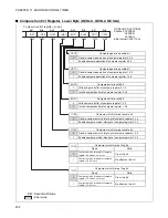
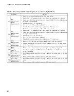
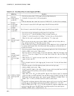
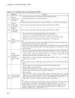
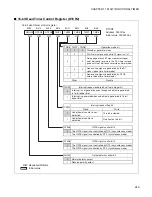
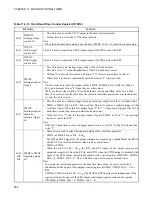
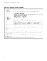
Table 11.4-8 Input Capture State Control Register (ch.2, ch.3), Lower Byte (ICSL23)
Bit Name
Function
bit7
ICP3:
Interrupt request
flag bit
(Input capture 3)
•
This bit is used as an interrupt request flag of the input capture 3.
•
This bit is set to "1" immediately when a valid edge of an external input pin is detected.
•
When a valid edge is detected while the interrupt enable bit (ICE3: bit5) is set, the interrupt
can be generated immediately.
•
When this bit is set to "0": Clears the bit.
•
Setting this bit to "1" has no effect on this bit.
•
When this bit is read to a read modify write instruction, "1" is always read.
bit6
ICP2:
Interrupt request
flag bit
(Input capture 2)
•
This bit is used as an interrupt request flag of the input capture 2.
•
This bit is set to "1" immediately when a valid edge of an external input pin is detected.
•
When a valid edge is detected while the interrupt enable bit (ICE2: bit4) is set, the interrupt
can be generated immediately.
•
When this bit is set to "0": Clears the bit.
•
Setting this bit to "1" has no effect on this bit.
•
When this bit is read to a read modify write instruction, "1" is always read.
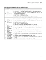
bit5
ICE3:
Interrupt request
enable bit
(Input capture 3)
•
This bit is used to enable an input capture interrupt request of the input capture 3.
•
When the interrupt flag bit (ICP3: bit7) is set while this bit is set to "1", the input capture 3
interrupt is generated.
bit4
ICE2:
Interrupt request
enable bit
(Input capture 2)
•
This bit is used to enable an input capture interrupt request of the input capture 2.
•
When the interrupt flag bit (ICP2: bit6) is set while this bit is set to "1", the input capture 2
interrupt is generated.
bit3
bit2
EG31, EG30:
Edge selection bit
(Input capture 3
•
These bits are used to specify the valid edge polarity of the external input for the input
capture 3.
•
These bits are used also to enable an operation of the input capture 3.
bit1
bit0
EG21, EG20:
Edge selection bit
(Input capture 2)
•
These bits are used to specify the valid edge polarity of the external input for the input
capture 2.
•
These bits are used also to enable an operation of the input capture 2.
Summary of Contents for FR60Lite
Page 3: ......
Page 5: ......
Page 115: ...100 CHAPTER 3 CPU AND CONTROL UNITS ...
Page 127: ...112 CHAPTER 4 I O PORTS ...
Page 143: ...128 CHAPTER 5 INTERRUPT CONTROLLER ...
Page 155: ...140 CHAPTER 6 EXTERNAL INTERRUPT AND NMI CONTROLLER ...
Page 197: ...182 CHAPTER 9 PPG Programmable Pulse Generator ...
Page 337: ...322 CHAPTER 13 UART ...
Page 417: ...402 CHAPTER 16 DMAC DMA Controller ...
Page 445: ...430 CHAPTER 17 FLASH MEMORY ...
Page 451: ...436 CHAPTER 18 SERIAL PROGRAMMING CONNECTION ...
Page 493: ...478 APPENDIX F Precautions on Handling ...
Page 494: ...479 INDEX INDEX The index follows on the next page This is listed in alphabetic order ...
Page 507: ...492 INDEX ...
Page 509: ......


