


293
CHAPTER 11 MULTIFUNCTIONAL TIMER
■
Notes on Using Waveform Generator
●
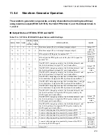
Cautions for setting via the program
•
Before changing the 16-bit dead timer control register's (DTCR0, DTCR1, DTCR2) TMD8, TMD5, and
TMD2 (higher-order bit is 10; lower-order bit is 2), TMD7, TMD4, and TMD1 (higher-order bit is 9;
lower-order bit is 1), or TMD6, TMD3, and TMD0 (higher-order bit is 8; lower-order bit is 0) during
waveform generator operation (DTCR0, DTCR1, DTCR2 register's TMD2 to TMD0, TMD5 to TMD3,
TMD8 to TMD6 is "001
B
", "010
B
", or "111
B
"), be sure that the trigger source and 16-bit dead timer are
not counting. If this operation is not performed, the output previously scheduled by the trigger causes an
unexpected waveform to be outputted from the RTO pins. However, normal RTO output will resume
after the timer underflows, or another trigger is generated by a new trigger source.
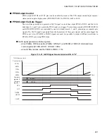
•
The trigger source is "H" level of RT when the DTCR0, DTCR1, and DTCR2 register's TMD8 to
TMD0 (higher-order bits are 10 to 8; lower-order bits are 2 to 0) is "001
B
"; RT rising edge when TMD8
to TMD0 bits are "010
B
"; RT rising or falling edge when TMD8 to TMD0 are "100
B
"; and PPG0 rising
edge or falling edge when TMD8 to TMD0 bits are "111
B
".
For example, if TMD8 to TMD0 bits change from "100
B
" to "111
B
", the following steps can be
executed.
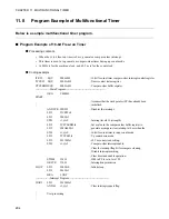
1. Set the 16-bit dead timer register (TMRRH0 to TMRRH2, TMRRL0 to TMRRL2) to an extremely
small value like "0001
H
".
2. RTO1, RTO3, and RTO5 output is awaited until "L" or "H" is set, and timer 0, 1, and 2 underflow.
3. Change the mode bits (TMD8 to TMD0) and corresponding settings.
4. A corrected output waveform appears at the RTO pins after 1 machine cycle.
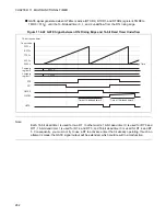
•
If a value is written to the 16-bit dead timer register (TMRRH0 to TMRRH2, TMRRL0 to TMRRL2)
during timer count, this new value is enabled during the next timer trigger. When accessing the timer
registers, be sure to use half-word or word transfer commands.
•
Only change the waveform control register 1 (SIGCR1) DCK2 to DCK0: bit4 to bit2 when the timers
are not counting.
•
Only change the waveform control register 1 (SIGCR1) NWS1 and NWS0: bit1 and bit0 when the noise
cancel feature is disabled.
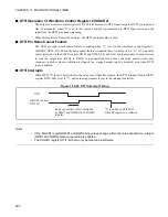
●
Note on interruption
•
If 1 is set in the 16-bit dead timer control register's (DTCR0, DTCR1, DTCR2) TMIF2 to TMIF0
(higher-order bit is 12; lower-order bit is 4), and then interrupt requests are enabled (DTCR0, DTCR1,
DTCR2 register's TMIE2 to TMIE0 (higher-order bit is 11; lower-order bit is 3) = 1), control cannot
return from interrupt processing. Always clear the TMIF bit.
•
Control cannot return from interrupt processing after setting "1" in the waveform control register 1
(SIGCR1) DTIF: bit7. Always clear the DTIF bit.
Summary of Contents for FR60Lite
Page 3: ......
Page 5: ......
Page 115: ...100 CHAPTER 3 CPU AND CONTROL UNITS ...
Page 127: ...112 CHAPTER 4 I O PORTS ...
Page 143: ...128 CHAPTER 5 INTERRUPT CONTROLLER ...
Page 155: ...140 CHAPTER 6 EXTERNAL INTERRUPT AND NMI CONTROLLER ...
Page 197: ...182 CHAPTER 9 PPG Programmable Pulse Generator ...
Page 337: ...322 CHAPTER 13 UART ...
Page 417: ...402 CHAPTER 16 DMAC DMA Controller ...
Page 445: ...430 CHAPTER 17 FLASH MEMORY ...
Page 451: ...436 CHAPTER 18 SERIAL PROGRAMMING CONNECTION ...
Page 493: ...478 APPENDIX F Precautions on Handling ...
Page 494: ...479 INDEX INDEX The index follows on the next page This is listed in alphabetic order ...
Page 507: ...492 INDEX ...
Page 509: ......


