


19
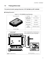
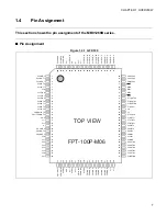
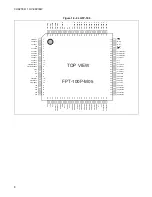
CHAPTER 1 OVERVIEW
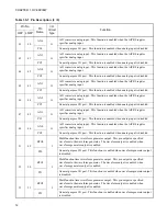
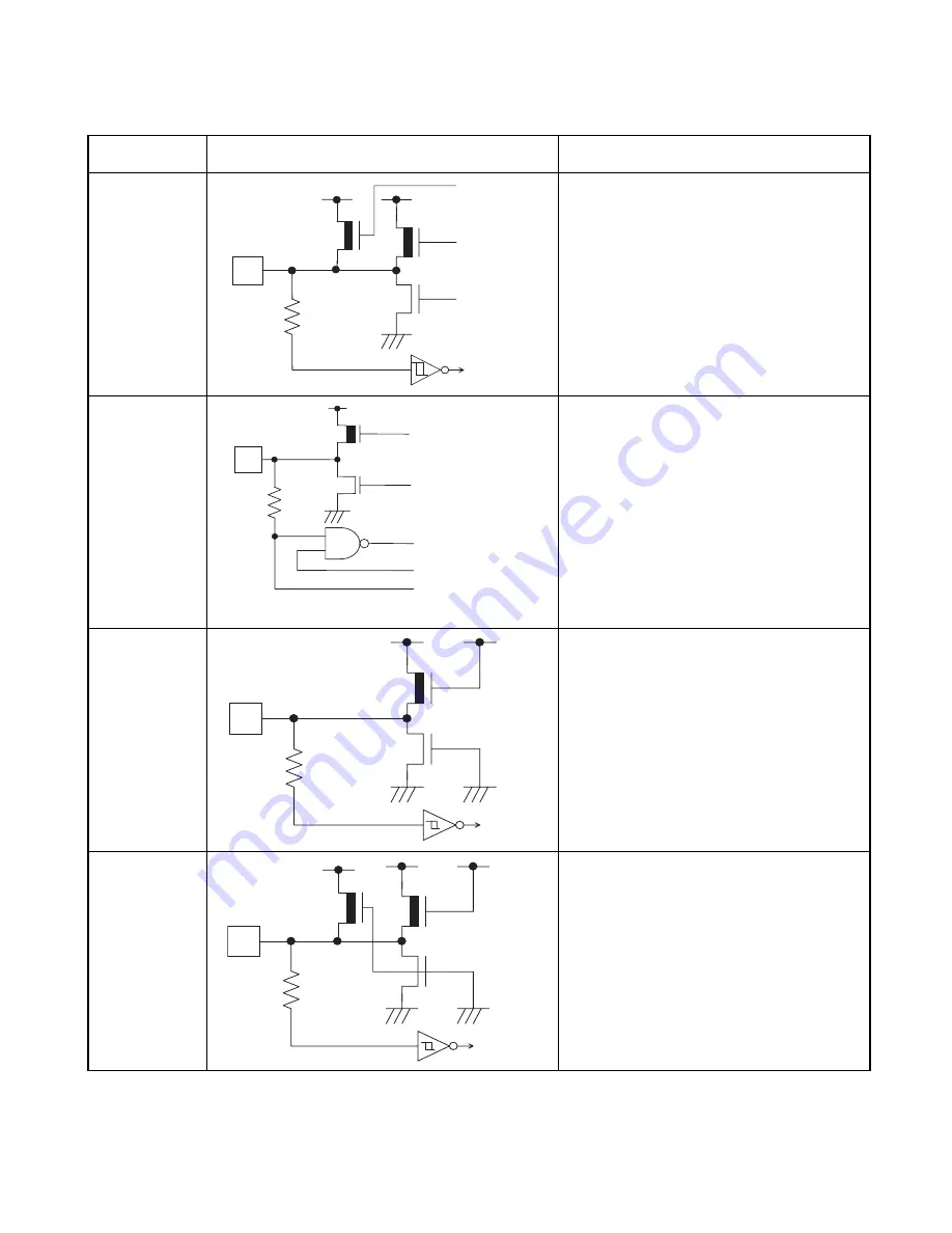
E
•
CMOS level output
•
CMOS level hysteresis input
•
No standby control
•
Control with pull-up resistor
Pull-up resistance = About 50 k
Ω
(Typ)
•
I
OL
= 4 mA
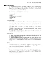
G
•
Analog/CMOS level I/O pins
- CMOS level output
- CMOS level input
(With standby control)
- Analog input
(The analog input is enabled with the
AICR's corresponding bit set to "1".)
•
I
OL
=4 mA
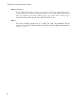
H
•
CMOS level hysteresis input
•
No standby control
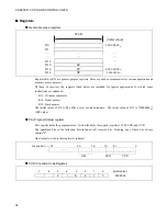
I
•
CMOS level hysteresis input
•
With pull-up resistor
Pull-up resistance = About 50 k
Ω
(Typ)
•
No standby control
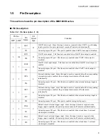
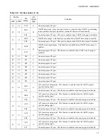
Table 1.6-1 Input/Output Circuit Type (2 / 3)
Classification
Circuit Type
Remarks
Digital input
Digital output
Digital output
Pull-up control
R
Digital output
Digital output
Digital input
Standby control
Analog input
R
Digital input
R
Digital input
R
R
Summary of Contents for FR60Lite
Page 3: ......
Page 5: ......
Page 115: ...100 CHAPTER 3 CPU AND CONTROL UNITS ...
Page 127: ...112 CHAPTER 4 I O PORTS ...
Page 143: ...128 CHAPTER 5 INTERRUPT CONTROLLER ...
Page 155: ...140 CHAPTER 6 EXTERNAL INTERRUPT AND NMI CONTROLLER ...
Page 197: ...182 CHAPTER 9 PPG Programmable Pulse Generator ...
Page 337: ...322 CHAPTER 13 UART ...
Page 417: ...402 CHAPTER 16 DMAC DMA Controller ...
Page 445: ...430 CHAPTER 17 FLASH MEMORY ...
Page 451: ...436 CHAPTER 18 SERIAL PROGRAMMING CONNECTION ...
Page 493: ...478 APPENDIX F Precautions on Handling ...
Page 494: ...479 INDEX INDEX The index follows on the next page This is listed in alphabetic order ...
Page 507: ...492 INDEX ...
Page 509: ......


