


74
CHAPTER 3 CPU AND CONTROL UNITS
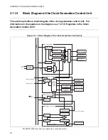
3.11.3
Clock Distribution
The operation clock signals for various functions are produced based on the base clock
signal generated from the source clock.
The MB91260B series has a total of three types of internal operation clock signals, each
of which can be set independently for the frequency divide ratio.
■
CPU Clock Signal (CLKB)
This clock signal is used for the CPU, internal memory, and internal buses.
The circuits using this clock signal include:
•
CPU
•
Internal RAM and internal ROM
•
Bit search module
•
I-bus, D-bus, F-bus, and X-bus
•
DMA controller
•
On-chip Debug Support Unit (DSU)
Do not set a combination of the multiplier and divide ratio which results in a frequency higher than the
maximum operating frequency.
■
Peripheral Clock Signal (CLKP)
This clock signal is used for peripheral resources and peripheral buses.
The circuits using this clock signal include:
•
Peripheral buses
•
Clock control unit (only the bus interface unit)
•
Interrupt controller
•
I/O ports
•
External interrupt inputs, UART, 16-bit timer, and other peripheral resources
Do not set a combination of the multiplier and divide ratio which results in a frequency higher than the
maximum operating frequency.
■
External Bus Clock Signal (CLKT)
This clock signal is used for the external extended bus interface.
The circuits using this clock signal include:
•
External extended bus interface
•
External CLK outputs
Do not set a combination of the multiplier and divide ratio which results in a frequency higher than the
maximum operating frequency. However, the MB91260B series does not support the external bus mode.
Summary of Contents for FR60Lite
Page 3: ......
Page 5: ......
Page 115: ...100 CHAPTER 3 CPU AND CONTROL UNITS ...
Page 127: ...112 CHAPTER 4 I O PORTS ...
Page 143: ...128 CHAPTER 5 INTERRUPT CONTROLLER ...
Page 155: ...140 CHAPTER 6 EXTERNAL INTERRUPT AND NMI CONTROLLER ...
Page 197: ...182 CHAPTER 9 PPG Programmable Pulse Generator ...
Page 337: ...322 CHAPTER 13 UART ...
Page 417: ...402 CHAPTER 16 DMAC DMA Controller ...
Page 445: ...430 CHAPTER 17 FLASH MEMORY ...
Page 451: ...436 CHAPTER 18 SERIAL PROGRAMMING CONNECTION ...
Page 493: ...478 APPENDIX F Precautions on Handling ...
Page 494: ...479 INDEX INDEX The index follows on the next page This is listed in alphabetic order ...
Page 507: ...492 INDEX ...
Page 509: ......


