138
CHAPTER 6 EXTERNAL INTERRUPT AND NMI CONTROLLER
■
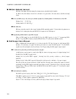
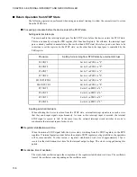
Return Operation from STOP State
The following operation is performed when using an external interrupt to allow the current circuit to return
from the STOP state.
●
Processing procedure before the device enters the STOP state
Setting external interrupts
You must enable the interrupt input pass for the STOP state before the device enters the STOP state.
This can be done by setting the PFR register (Port Function Register). Nevertheless, the interrupt input
pass is already enabled in normal states (those other than STOP state); therefore, you do not have to be
conscious to set the register. In the STOP state, on the other hand, the input pass is controlled by the
PFR register.
Inputting external interrupts
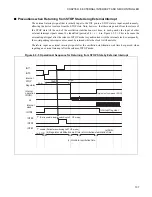
When allowing the device to return from the STOP state, external interrupt signals are in such a state
that they send input signals asynchronously. As soon as this interrupt input is asserted, the internal
STOP signal is caused to fall. At the same time, the external interrupt circuit switches its mode to
synchronize the interrupt input of other levels.
●
Regulator stabilization wait time
When the internal STOP signal falls, the device starts switching from the STOP regulator to the RUN
regulator. If internal operation starts before the output of RUN regulator voltage stabilizes, the operation
will become unstable. For this reason, a regulator stabilization wait time of approximately 12
µ
s is
secured as the stabilization wait time for the internal output voltage. The clock is stopped during this
period.
●
Oscillation time of oscillator
The clock starts oscillation upon the completion of the regulator stabilization wait time. The oscillation
time of the oscillator varies depending on the oscillator used.
Pin name
Setting for returning from STOP state by external interrupt
P63/INT9
Set bit 3 in PCR6 to "0".
P62/INT8
Set bit 2 in PCR6 to "0".
P26/INT7
Set bit 7 in PCR2 to "0".
P27/INT6
Set bit 6 in PCR2 to "0".
P62/INT5/PPG0
Set bit 1 in PCR6 to "0".
P60/INT4/CKI
Set bit 0 in PCR6 to "0".
P57/INT3
Set bit 7 in PFR5 to "0".
P56/INT2
Set bit 6 in PFR5 to "0".
P55/INT1
Set bit 5 in PFR5 to "0".
P54/INT0
Set bit 4 in PFR5 to "0".
Summary of Contents for FR60Lite
Page 3: ......
Page 5: ......
Page 115: ...100 CHAPTER 3 CPU AND CONTROL UNITS ...
Page 127: ...112 CHAPTER 4 I O PORTS ...
Page 143: ...128 CHAPTER 5 INTERRUPT CONTROLLER ...
Page 155: ...140 CHAPTER 6 EXTERNAL INTERRUPT AND NMI CONTROLLER ...
Page 197: ...182 CHAPTER 9 PPG Programmable Pulse Generator ...
Page 337: ...322 CHAPTER 13 UART ...
Page 417: ...402 CHAPTER 16 DMAC DMA Controller ...
Page 445: ...430 CHAPTER 17 FLASH MEMORY ...
Page 451: ...436 CHAPTER 18 SERIAL PROGRAMMING CONNECTION ...
Page 493: ...478 APPENDIX F Precautions on Handling ...
Page 494: ...479 INDEX INDEX The index follows on the next page This is listed in alphabetic order ...
Page 507: ...492 INDEX ...
Page 509: ......

