251
CHAPTER 11 MULTIFUNCTIONAL TIMER
11.4.12
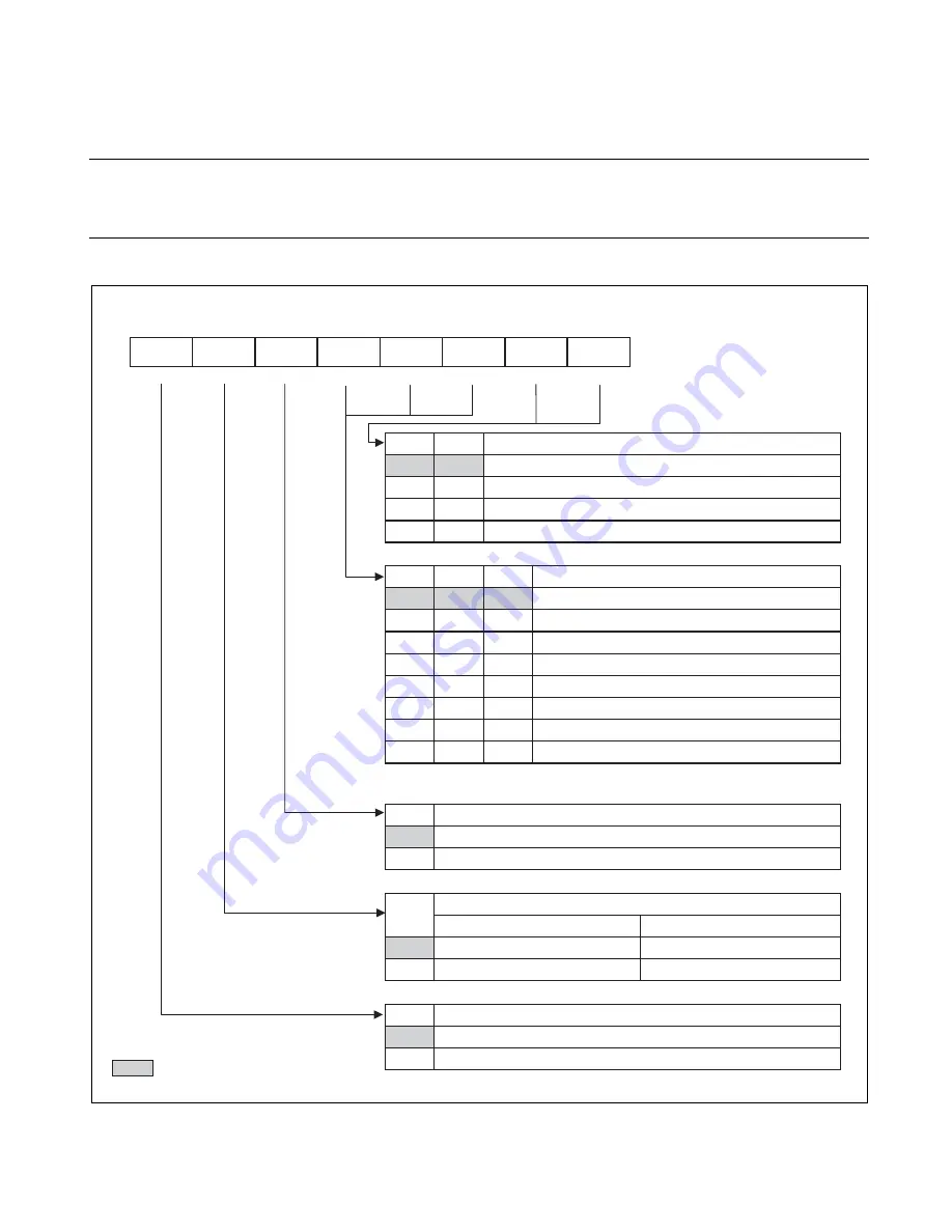
Waveform Control Register (SIGCR1, SIGCR2)
The waveform control register is used to control the operating clock frequency, enable
the noise cancel feature, enable DTTI input, and control DTTI interrupts.
■
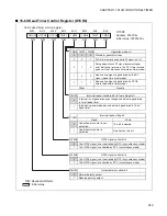
Waveform Control Register 1 (SIGCR1)
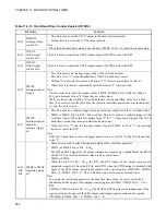
NWS1 NWS0
DTTI noise
w
idth selection bit
0
0
Cancel noise of 4cycles
0
1
Cancel noise of 8cycles
1
0
Cancel noise of 16cycles
1
1
Cancel noise of 32cycles
DCK2 DCK1
DCK0
Operation clock selection bit
0
0
0
0
1
0
0
0
1
1
0
1
1
1
0
φ
(62.5ns,
φ
=16MHz)
φ
/2 (125ns,
φ
=16MHz)
φ
/4 (250ns,
φ
=16MHz)
φ
/8 (500ns,
φ
=16MHz)
φ
/16 (1ms,
φ
=16MHz)
φ
/32 (2ms,
φ
=16MHz)
φ
/64 (4ms,
φ
=16MHz)
1
1
Disable
φ
: Machine cycle
NRSL
Noise cancel function valid bit
0
Noise cancel circuit of DTTI input is invalid.
1
Noise cancel circuit of DTTI input is valid.
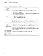
DTTI interrupt flag bit
DTIF
Read
Write
0
No interrupt request
This bit is cleared.
1
Interrupt request
No effect on this bit.
DTIE
DTTI input valid bit
0
Invalid DTTI input
1
Valid DTTI input
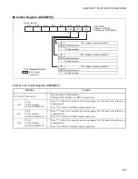
DTIE
DTIF
NRSL
DCK2
DCK1
DCK0
NWS1
NWS0
SIGCR1
Address: 0000C9
H
Waveform control register 1
Initial value: 00000000
B
Bit7
Bit6
Bit5
Bit4
Bit3
Bit2
Bit1
Bit0
R/W
R/W
R/W
R/W
R/W
R/W
R/W
R/W
0
1
1
0
0
1
1
R/W: Readable/Writable
: Initial value
Summary of Contents for FR60Lite
Page 3: ......
Page 5: ......
Page 115: ...100 CHAPTER 3 CPU AND CONTROL UNITS ...
Page 127: ...112 CHAPTER 4 I O PORTS ...
Page 143: ...128 CHAPTER 5 INTERRUPT CONTROLLER ...
Page 155: ...140 CHAPTER 6 EXTERNAL INTERRUPT AND NMI CONTROLLER ...
Page 197: ...182 CHAPTER 9 PPG Programmable Pulse Generator ...
Page 337: ...322 CHAPTER 13 UART ...
Page 417: ...402 CHAPTER 16 DMAC DMA Controller ...
Page 445: ...430 CHAPTER 17 FLASH MEMORY ...
Page 451: ...436 CHAPTER 18 SERIAL PROGRAMMING CONNECTION ...
Page 493: ...478 APPENDIX F Precautions on Handling ...
Page 494: ...479 INDEX INDEX The index follows on the next page This is listed in alphabetic order ...
Page 507: ...492 INDEX ...
Page 509: ......

