364
CHAPTER 15 MULTIPLICATION AND ADDITION CALCULATOR
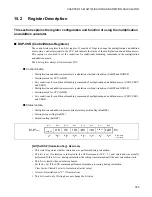
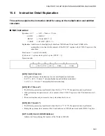
[bit5 to bit0] Y-Addr (Y-RAM Address)
•
Address bits for specifying the location of the Y data in Y-RAM.
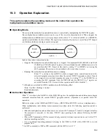
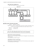
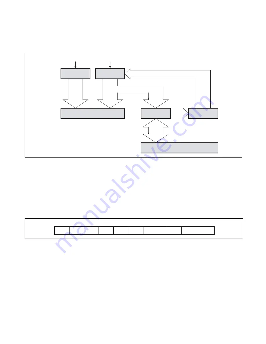
Figure 15.4-1
■
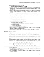
STR Instruction (Transition Instruction)
Operation:
Data RAM
←
Accumulator
Explanation: Convert the 40-bit accumulator value to a 16-bit value in accordance with the RND, CLP, and
SLQ flags. Store the result in the data RAM specified by the SLY flag and X/Y-Addr.
Word count:
1 word (16-bit width)
Cycle count:
1 system clock cycle
Operation code:
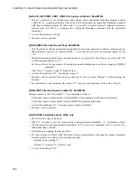
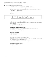
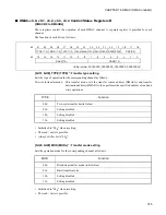
[bit13] HLT (HLT instruction indicating flag)
Setting this bit causes the multiplication and addition macro to halt program execution after instruction
execution completes.
Clears the RunDSP flag in the DSP-CSR register.
[bit12] SIRQ (INT instruction indicating flag)
Setting this bit causes an interrupt request to be sent to the CPU after instruction execution completes, then
sets the IrqDSP flag in the DSP-CSR register.
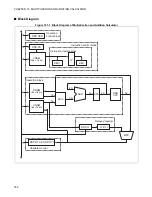
X-RAM
X-Addr
X data
Y-RAM
Y-Addr
Y data
Multiply-Add Calculator
if (STLY==1) then Store
DSP-Y
if (LDLY==1) then Load
LY-DLY
CPU bus
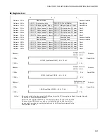
15
14
13
12
11
10
9 . . . . . . . 7
6
5 . . . . . . . . . . . 0
0
1
HLT
SIRQ
RND
CLP
SLQ
SLY
X- and Y-Addr
Summary of Contents for FR60Lite
Page 3: ......
Page 5: ......
Page 115: ...100 CHAPTER 3 CPU AND CONTROL UNITS ...
Page 127: ...112 CHAPTER 4 I O PORTS ...
Page 143: ...128 CHAPTER 5 INTERRUPT CONTROLLER ...
Page 155: ...140 CHAPTER 6 EXTERNAL INTERRUPT AND NMI CONTROLLER ...
Page 197: ...182 CHAPTER 9 PPG Programmable Pulse Generator ...
Page 337: ...322 CHAPTER 13 UART ...
Page 417: ...402 CHAPTER 16 DMAC DMA Controller ...
Page 445: ...430 CHAPTER 17 FLASH MEMORY ...
Page 451: ...436 CHAPTER 18 SERIAL PROGRAMMING CONNECTION ...
Page 493: ...478 APPENDIX F Precautions on Handling ...
Page 494: ...479 INDEX INDEX The index follows on the next page This is listed in alphabetic order ...
Page 507: ...492 INDEX ...
Page 509: ......

