background image


9  


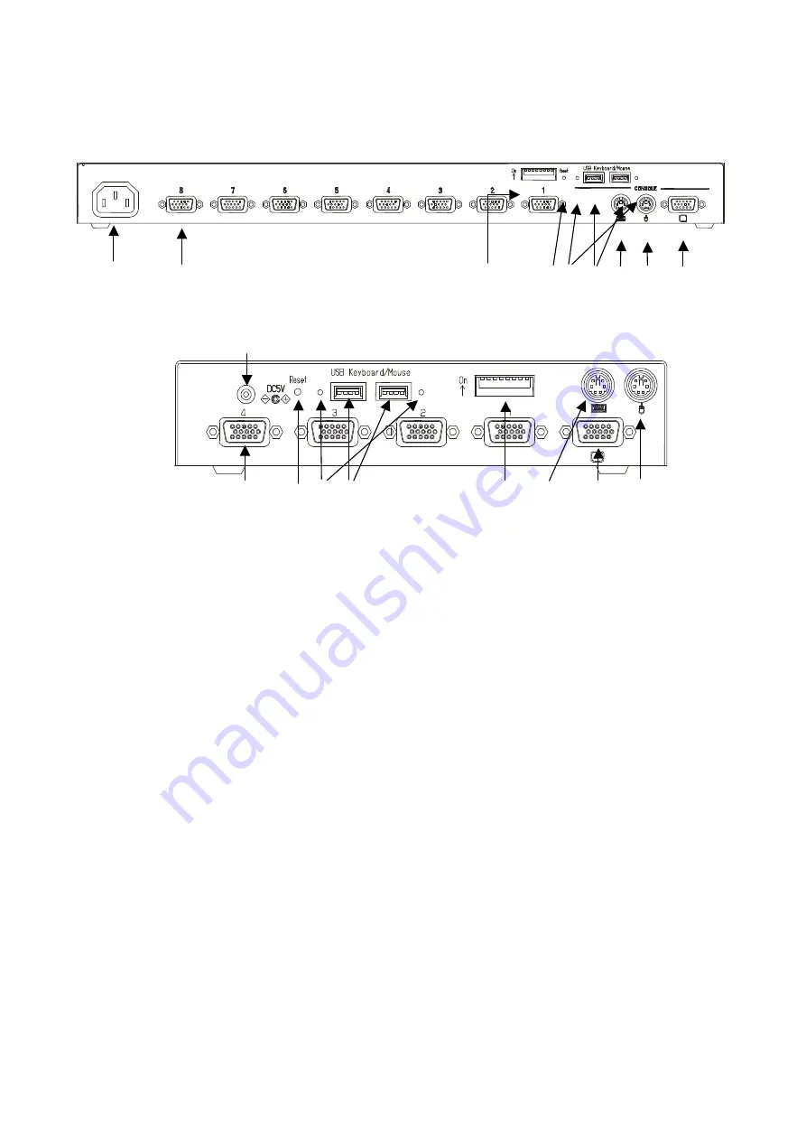
3.2 Rear Panel 


     6)        7)                                                                                13)       5) 9)  8) 10)  11)  12) 


8 Port Rear Panel 


              14)


                7)      5)  9)  8)                   13)   10)    12)    11)


4 Port Rear Panel 


6)  Power cable connector 

Connect to a 100 to 240V AC electric outlet. 

7)  Connectors for hosts [1 through 8] 

Connect each port (1 through 8) on this device to the relevant host’s keyboard, mouse 
and monitor connectors with the special cable. 

8)  USB keyboard / mouse Connector 

Connect a USB keyboard / mouse here. 
(Cannot be used concurrently with a PS/2 type keyboard and mouse. USB keyboard / 
mouse have priority over PS/2 keyboard / mouse) 

9)  USB keyboard / mouse status LEDs 

Green:  This port can use or using. 
Red  :  Over current was drawn from this port. Not in work. 
 

   Unplug the device and push a reset_sw. 

unlit  :  Unsupported device or some error has occurred in this port. 
 

   Unplug the device or push a reset_sw. 

10) PS/2 Keyboard connector 

Connect a PS/2 keyboard here. 
(Cannot be used concurrently with a USB type keyboard) 

11) PS/2 Mouse connector 

Connect a PS/2 mouse here. 
(Cannot be used concurrently with a USB type mouse) 

12) Monitor Connector 

Connect a monitor here.


13) DIP Switches   

Use for a variety of settings. Numbered from left side while facing the switches starting 
from 1,2…8; up is on and down is off.   

14) AC adapter connector   

Connect the AC adapter here. Do not use any AC adapter other than the one provided 
with the switch device. 


Summary of Contents for FS-1004MU

Page 1: ...SERVIS KVM Multi Platform USB Emulation Server Intelligent Switch for Multi Platform For IA and UNIX servers FS 1004MU FS 1008MU User s Manual FUJITSU COMPONENT LIMITED 050209 ...

Page 2: ...d and found to comply with the limits for a Class B digital device pursuant to Part 15 of the FCC Rules These limits are designed to provide reasonable protection against harmful interference in a residential installation This equipment generates uses and can radiate radio frequency energy and if not installed and used in accordance with the instruction may cause harmful interference to radio comm...

Page 3: ...TING STARTED 13 5 2 CONNECTING THE HOSTS USING SINGLE SWITCH DEVICE 13 5 3 CONNECTING THE HOSTS USING CASCADED CONNECTIONS 14 6 OPERATION HOST SELECTION 16 6 1 HOST SELECTION BY HOST SELECTOR BUTTONS NORMAL MODE 16 6 2 HOST SELECTION BY KEYBOARD HOT KEY MODE 16 6 2 1 HOT KEY MODE A 17 6 2 2 HOT KEY MODE B 21 6 3 SHOWING HIDING HOST NAMES FUNCTION 21 6 4 EDID SETTING MODE 22 7 SPECIFICATIONS 24 8 O...

Page 4: ... 4 port and 8 port setups Unless specifically noted all explanations assume an 8 port setup KVM Switch Keyboard Video Mouse switch 1 1 Conventions Symbols and terminology that are used in this manual are described below This symbol indicates the possibility of physical damage such as damage to the KVM switch or physical injury which may result if the KVM switch is operated incorrectly by ignoring ...

Page 5: ...e connecting or disconnecting any of the connectors Also be sure to discharge any static electricity Connecting or disconnecting the connectors while carrying a static charge or while the power to the host is on may damage the host or this device Please note that damage of this kind is not covered by the warranty l Only PC AT compatible computers and SUN workstations can be hooked up to this devic...

Page 6: ... high resolution screen quality such as ghosts or blurring may be due to the monitor cable or video card Also the screen may not display normally sometimes depending on the particular combination of display and video card If this happens try using a high grade cable or video card and altering the connection environment l The monitor cable connector is a DB 15 HD type You will need a monitor conver...

Page 7: ... or parts or replacing with a refurbished or alternative product or issuing credit for the purchase price if paid for such Product that was defective at the time delivered to Purchaser provided that Fujitsu will not be liable under this warranty unless i Fujitsu is promptly notified in writing upon the discovery of defects by Purchaser ii the defective unit is returned to Authorized Company transp...

Page 8: ...devices l There is a power and voltage monitoring circuit built in to the device to let you know if the AC cord becomes disconnected or the internal fuse blows l Both PS 2 and USB keyboards are supported l Both PS 2 and USB mice are supported The following PS 2 mice are supported 2 3 button mice each type of wheel mice Microsoft IntelliMouse Microsoft IntelliMouse Explorer Logitech Logicool MouseM...

Page 9: ...rformed at this time 3 Host Selector Buttons Press a button to select its host You can select hosts even if the POWER LED is not lit 4 Select LED Lights up when the host is selected It flashes quickly when in the hot key mode 5 Reset Switch Normally this switch is not used Use this switch when selection is not possible or when the keyboard or mouse cannot be operated Press it lightly with the tip ...

Page 10: ... Green This port can use or using Red Over current was drawn from this port Not in work Unplug the device and push a reset_sw unlit Unsupported device or some error has occurred in this port Unplug the device or push a reset_sw 10 PS 2 Keyboard connector Connect a PS 2 keyboard here Cannot be used concurrently with a USB type keyboard 11 PS 2 Mouse connector Connect a PS 2 mouse here Cannot be use...

Page 11: ...e Setting ON the switch device is always ON OFF the switch device turns ON if any connected host is turned ON The country code language settings are as follows Country Setting SW4 SW5 SW6 SW7 Japan ON ON ON ON US ON ON ON OFF UK ON ON OFF ON German ON ON OFF OFF French ON OFF ON ON Spanish ON OFF ON OFF Swedish ON OFF OFF ON The country code language settings are as follows Country Setting SW4 SW5...

Page 12: ...11 ...
Page 13: ...et large to the rear panel side of the switch device use the attached M3 screws 6 pcs 4 Detach the console panel connector cable from the console panel before mounting it in the rack This makes it easy to mount the switch device 5 Fix the console panel to the front side of the rack with screws 6 Fix the rear panel to the rear of the rack with the screws 7 Reattach the console cable detached in ste...

Page 14: ... connect b next connect the switch device s host port connector Mini D Sub 15 pin female to the special connector black connect c 2 Connect hosts 2 through 8 in the same manner PS 2 Keyboard Mouse Monitor USB Keyboard Mouse Monitor This switch device and the hosts should use a three line type power cable with the ground line on the power cable grounded If you use a two line plug adapter be sure to...

Page 15: ...ting mode using NEXT PAGE and press the Enter key 7 Select each port in turn and confirm the attached host is started up and using the correct settings 8 If the keyboard mouse or monitor is not set correctly adjust the settings and restart the system 5 3 Connecting the hosts using cascaded connections 1 Connect the hosts one through eight to the second level of switch devices called slaves in the ...

Page 16: ...Plug n Play data setting After connect the monitor to the switch device push reset_sw or open the OSD via the hot key press then go to EDID setting mode using NEXT PAGE and press the Enter key 8 Select each port in turn and confirm the attached host is started up and using the correct settings 9 If the keyboard mouse or monitor are not set correctly adjust the settings and restart the system This ...

Page 17: ... during auto scan Exit Auto Scan Mode if you want to move to the Hot Key Mode Exit auto scan with the following method Auto Scan Button or Enter Key Switches to the currently displayed screen ESC Key Returns you to the host whereAuto scan started 6 2 Host Selection by Keyboard Hot Key Mode The Hot Key Mode may be activated usingany of the following three methods Hot key modeA Press Ctrl Alt Shift ...

Page 18: ...currently selectable with the arrow cursor keys 4 The bottom of the screen shows simple explanations of allowed key operations 5 The mark shows the currently selected host channel 6 Green numbers 1 8 or F1 F8 show the connected host is ON 7 Depending on whether the selected channel has a cascaded slave device attached to it or not the OSD master device display section 1 above changes as follows No...

Page 19: ...a cascade connected channel is selected the state of the selected slave device is shown on the right side of the OSD 3 If a cascade connected channel is selected pressing the cursor key causes control to switch to the right slave side of the OSD with the currently selected cascaded host shown in purple Press the cursor key to return control to the left master side of the OSD 4 On the right side of...

Page 20: ...ed and the OSD reverts to the normal console Hot Key Mode is finished When selecting a port in a cascaded connection select the port on the master side firstly Then select and switch to the port on the slave side Direct Switching Via Host Selector Buttons Press the Selector Button 1 8 on the switch device s console panel to select a host To select a cascaded host press the Selector Button 1 8 on t...

Page 21: ...onfirmed name revert to original name 5 A host name may be up to 14 characters long 6 Any of the following 47 characters may be used ABCDEFGHIJKLMNOPQRSTUVWXYZ1234567890 and Space Changing a master side name Changing a slave side name Single KVM setup has no blue area 7 Pressing the Reset Switch with the 1 and 3 front switches also held down causes any set names to be discarded and reverts the dev...

Page 22: ...ground back to blue exit Hot Key Mode either press a number key combination or press the Esc key or the Enter key If the 0 key is pressed while the text background is red Auto Scan Mode is entered Auto Scan Mode may be cancelled as follows Enter key Console switches to the currently displayed screen host Esc key Console reverts to the host active beforeAuto Scan Mode was entered 6 3 Showing Hiding...

Page 23: ...d from the monitor connected to the console port and written to the internal ROM After the ROM has been written the message PNP MONITOR is displayed When EDID information cannot be retrieved from the connected monitor the message DEFAULT MONITOR is displayed and 00 is written to the ROM If a new monitor is connected and the EDID Setting performed the internal ROM setting is subsequently transmitte...

Page 24: ...r it is possible to display an interlaced signal with a resolution of 1152 x 864 1280 x 1024 or 1600 x 1200 However at resolutions lower than this and the display may extend beyond the edges of the screen When push the Reset Switch EDID setting is also done automatically CAUTION ...

Page 25: ...PS 2 Mini DIN 6PFemale x 1 Purple PS 2 Mouse PS 2 Mini DIN 6P Female x 1 Green USB Keyboard Mouse USB typeAX 2 Console Ports Monitor Mini D SUB 15P Female x 1 Blue OSD Modes Manual Hot Key Mode Auto Scan Mode Auto Scan Intervals 3 5 10 default 20 40 60 seconds Monitor Resolution Refresh Rate 1600 x 1200 Max 75Hz Monitor Plug Play Function VESA DDC2 Compatible Voltage DC5V AC100V toAC240V 50 60Hz C...

Page 26: ...NC14000 B203 PS 2 cable USB cable Sun cable Combined Keyboard Mouse Monitor Cable 5 0m NC14000 B605 NC14000 B105 NC14000 B205 PS 2 cable USB cable Sun cable l AC Cables Item Product ID Remark For USA NC14004 B074 NC14004 B077 8Port KVM 4Port KVM ACAdapter For EUROPE NC14004 B075 NC14004 B078 8Port KVM 4Port KVM ACAdapter For UK NC14004 B076 NC14004 B079 8Port KVM 4Port KVM ACAdapter l Misc Item Pr...

Page 27: ... is defective Confirm the connector connection Replace with a different cable If this solves the problem replace with a new cable Wrong resolution Adjust the resolution or use the monitor function Window shifts or does not display when switching Unsupported monitor or cannot synchronize Replace with a supported monitor multisync Use the monitor function Device enters Hot Key Mode The device goes i...

Page 28: ...7 F8 F9 F10 F11 F12 Print Screen Scroll Lock Pause Break SysRq Home End Num Lock 7 Home 8 6 3 2 4 1 5 0 Enter Tab Caps Lock Shift Shift Ctrl Alt Alt Page Up Page Down 9 Esc F1 F2 F3 F4 F5 F6 F7 F8 F9 F10 F11 F12 Print Screen Scroll Lock Pause Break SysRq Home End Num Lock 7 Home 8 6 3 2 4 1 5 0 Enter Tab Caps Lock Shift Shift Ctrl Page Up Page Down Power Vol Vol Mute Alt Ctrl Fn Compose ...

Page 29: ...ock Tab 0 Ins Del 1 2 3 5 6 4 7 8 9 Num Lock Scroll Lock Break Pause SysRq Print Screen F12 F11 F10 F9 F8 F7 F6 F5 F4 F3 F2 F1 Esc Shift Help Ctrl Alt Com pose Alt Graph Shift Caps Lock Tab 0 Ins Del 1 2 3 5 6 4 7 8 9 Num Lock Scroll Lock Break Pause SysRq Print Screen F12 F11 F10 F9 F8 F7 F6 F5 F4 F3 F2 F1 Esc Shift Shift Help Ctrl Alt Ctrl ...

Page 30: ...1 2 3 4 5 6 7 8 SlaveUnitPort 1 NO NAME 1 2 3 4 5 6 7 8 SlaveUnitPort 5 NO NAME 1 2 3 4 5 6 7 8 SlaveUnitPort 2 NO NAME 1 2 3 4 5 6 7 8 SlaveUnitPort 3 NO NAME 1 2 3 4 5 6 7 8 SlaveUnitPort 4 NO NAME 1 2 3 4 5 6 7 8 SlaveUnitPort 7 NO NAME 1 2 3 4 5 6 7 8 SlaveUnitPort 6 NO NAME 1 2 3 4 5 6 7 8 SlaveUnitPort 8 NO NAME 1 2 3 4 5 6 7 8 ...

Page 31: ... in Japan Alltrademarksorregisteredtrademarksarethepropertyoftheirrespective owners Theinformationcontainedinthis document has been carefully checked and is believed to be reliable However FUJITSU COMPONENT LIMITED FCL oritsaffiliatesassumenoresponsibilityforinaccuracies Theinformation containedinthisdocument does not convey any license under the copyrights patent rights or trademarks claimed and ...

Page 32: ...31 This manual is made of recycled paper ...

Reviews: