4.2 Nand Flash
Hardware Setting
None
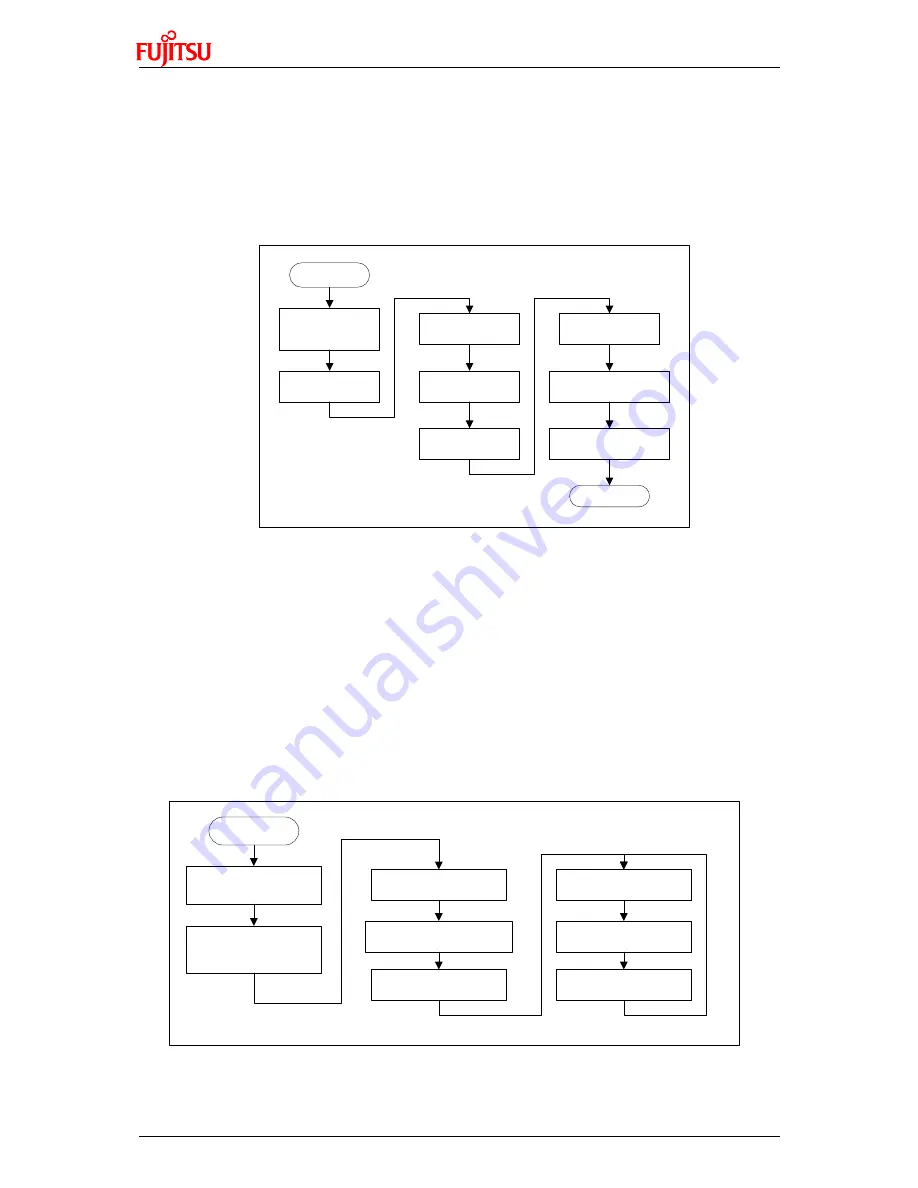
Flowchart
Start
Initial external bus
(Use CS7 area,
8 bit data width)
Read Flash ID
Erase page 11 of
block 0
Write data into
page 11 of block 0
Read data from
page 11 of block 0
Erase page 20 of
block 100
Write data into page
20 of block 100
Read data from page
20 of block 100
End
Figure 4-4: Nand Flash Sample Code Flowchart
Usage
1) Open Nand Flash sample project, and start debug.
2) Use “step over” to debug, and watch local variable “flash_id”, “buf”.
4.3 RTC
Hardware Setting
It is an
option
that user can user external battery to supply power for RTC module
(RX8025-T) so that the date and time can be stored after system power shut down.
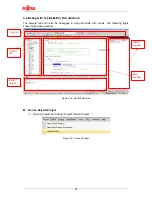
Flowchart
Start
Initial MFS channel 5
(set IIC mode)
Enable FOE signal
(FOUT output 32.768khz
wave after it is enabled)
Write 8 to hour register
Write 30 to minute register
Write 0 to second register
Read to second register
Read to minute register
Read to hour register
Figure 4-5: RTC Sample Code Flowchart
16


