


01-19
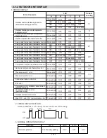
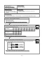
22. DEFROST OPERATION CONTROL
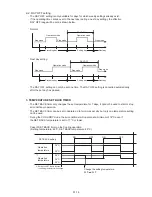
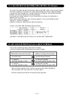
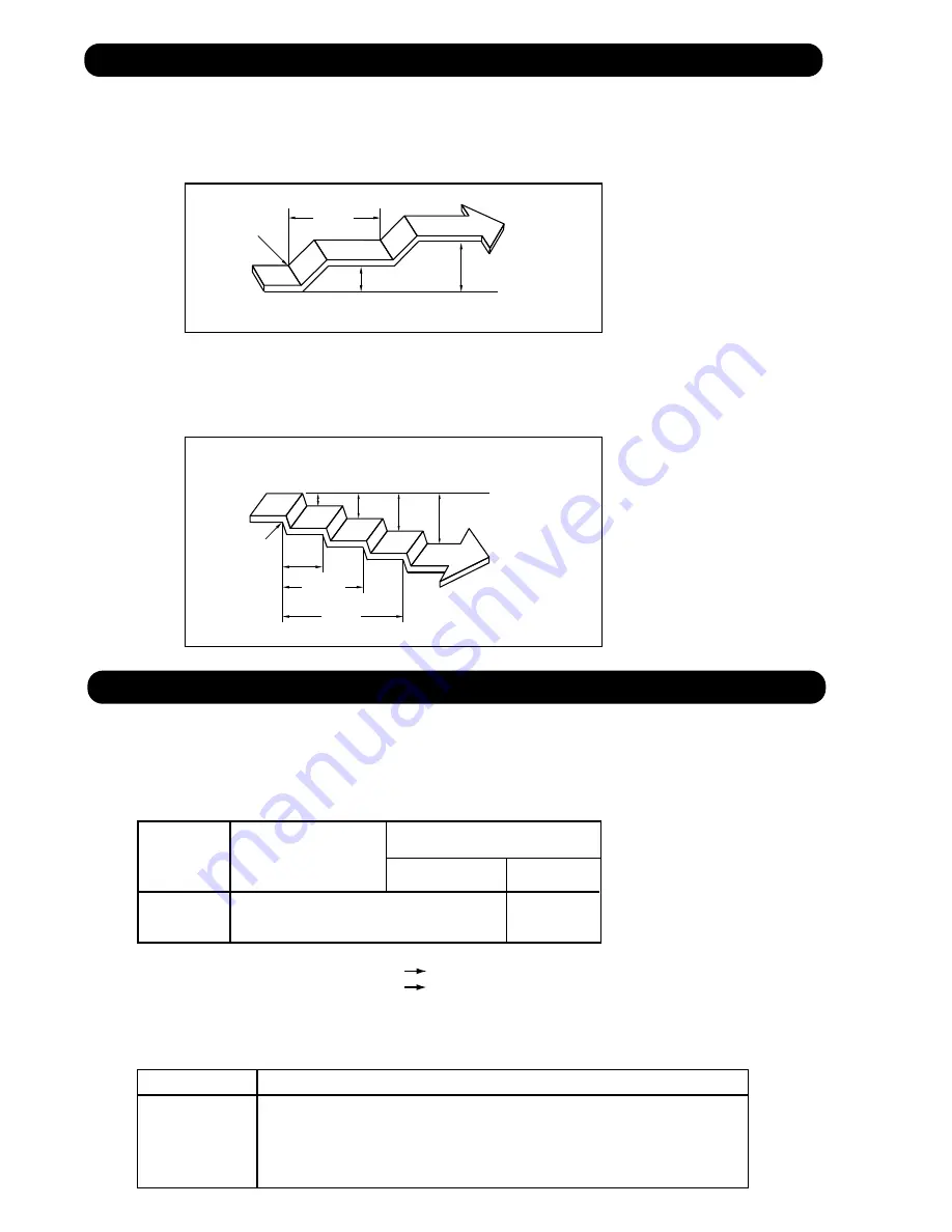
1. CONDITION OF STARTING THE DEFROST OPERATION
The defrost operation starts when the outdoor heat exchanger temperature sensor detects
the temperature lower than the values shown in Table 9.
(Table 9 : Condition of starting Defrost Operation)
Less than 6 min. *1
or 10min. *2
2. CONDITION OF THE DEFROST OPERATION COMPLETION
Defrost operation is released when the conditions become as shown in Table 10.
(Table 10 : Defrost Release Condition)
Release Condition
Outdoor heat exchanger temperature sensor value is higher than 53.6°F(12°C) or
Compressor operation time has passed 15 minutes.
AOU24RML
AOU36RML
AOU24RML
AOU36RML
*3. Outdoor temp. > 30.2°F (-1°C)
*4. Outdoor temp. < 30.2°F (-1°C)
*2. Compressor stop time: Below 20min. Select 6min.
Above 20min. Select 10min.
After 6 min. *1
or 10min. *2
Compressor integrating
operation :Less than 45min.
Compressor integrating
operation :45min and over
17.6
°
F(-8
°
C) *3
14
°
F (-10
°
C) *4
Does not operate
=
*1. It means contiguous operation time.
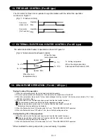
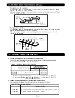
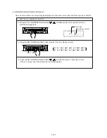
21. ENERGY SAVE FUNCTION (For AR type)
1. During Cooling / Dry operation:
The thermostat temperature setting increases by 1 degC as soon as the ENERGY SAVE button is pressed,
and then increases by 1 degC after 1 hour later.
Afterwards, energy consumption is saved by continuing to cool or dry at a thermostat temperature of 2 degC
higher than setting temperature.
2. During Heating operation:
The thermostat temperature setting decreases by 1 degC as soon as the ENERGY SAVE button is pressed,
and then decreases by another 1 degC every 30 minutes.
Afterwards, energy consumption is saved by continuing to heat at a thermostat temperature of 4 degC
lower than setting temperature.
1hour.
1 degC
2 degC
ENERGY
SAVE ON
Setting
temperature
1degC
2degC 3degC 4degC
30min.
1 hour.
1 hour
30 min.
ENERGY
SAVE ON
Setting
temperature
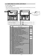
Summary of Contents for Inverter Halcyon ASU12RMLQ
Page 3: ...1 DESCRIPTION OF EACH CONTROL OPERATION R410A WALL MOUNTED DUCT CASSETTE type INVERTER MULTI ...
Page 26: ...2 TROUBLE SHOOTING R410A WALL MOUNTED DUCT CASSETTE type INVERTER MULTI ...
Page 76: ...3 REPLACEMENT PARTS R410A WALL MOUNTED DUCT CASSETTE type INVERTER MULTI ...
Page 77: ...REPLACEMENT PARTS 03 01 Models ASU9RMLQ ASU12RMLQ ASU18RMLQ INVERTER ...
Page 78: ...REPLACEMENT PARTS 03 02 Models ASU9RMLQ ASU12RMLQ ASU18RMLQ ...
Page 79: ...Model ARU9RML 03 03 REPLACEMENT PARTS ...
Page 80: ...Model ARU9RML 03 04 REPLACEMENT PARTS ...
Page 81: ...Models ARU12RML ARU18RML 03 05 REPLACEMENT PARTS ...
Page 82: ...Models ARU12RML ARU18RML 03 06 REPLACEMENT PARTS ...
Page 83: ...Models ARU9RML ARU12RML ARU18RML 03 07 REPLACEMENT PARTS ...
Page 84: ...40 Models AUU9RML AUU12RML AUU18RML REPLACEMENT PARTS ...
Page 85: ...41 Models AUU9RML AUU12RML AUU18RML CONTROL UNIT REPLACEMENT PARTS ...
Page 86: ...38 CASSETTE TYPE DECORATION PANEL UTG UFUB W REPLACEMENT PARTS ...
Page 88: ...REPLACEMENT PARTS 03 08 Model AOU24RML AOU24RML1 ...
Page 89: ...REPLACEMENT PARTS 03 09 Model AOU24RML AOU24RML1 ...
Page 90: ...REPLACEMENT PARTS 03 10 Model AOU24RML AOU24RML1 ...
Page 92: ...REPLACEMENT PARTS 03 12 Model AOU36RML AOU36RML1 ...
Page 93: ...REPLACEMENT PARTS 03 13 Model AOU36RML AOU36RML1 ...
Page 94: ...REPLACEMENT PARTS 03 14 Model AOU36RML AOU36RML1 ...
Page 141: ...4 APPENDING DATA R410A WALL MOUNTED DUCT CASSETTE type INVERTER MULTI 1 PT CHART ...
Page 145: ...1116 Suenaga Takatsu ku Kawasaki 213 8502 Japan GS06082006 JUN 2006 Printed in Japan ...


