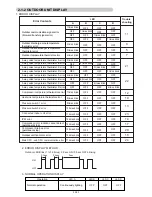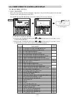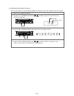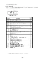
23. VARIOUS PROTECTIONS
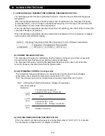
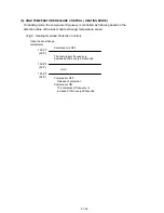
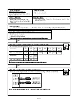
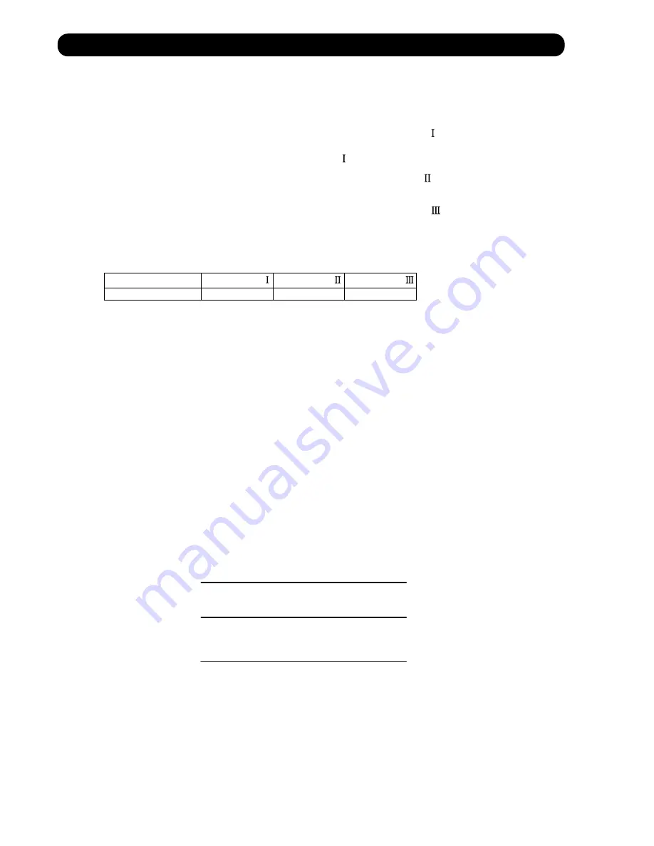
(1). DISCHARGE GAS TEMPERATURE OVERRISE PREVENSION CONTROL
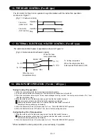
The discharge gas thermosensor (discharge thermistor : Outdoor side) will detect discharge gas
temperature.
AOU24/36RML
230°F(110°C)
212°F(100°C)
239°F(115°C)
When the discharge temperature becomes higher than Temperature ,the compressor frequency
is decreased 20 Hz, and it continues to decrease the frequency for 20 Hz every 120 seconds until
the temperature becomes lower than Temperature .
When the discharge temperature becomes lower than Temperature ,the control of the control of the
compressor frequency is released.
When the discharge temperature becomes higher than Temperature ,the compressor is stopped
and the indoor unit LED starts blinking.
(Table 11 : Discharge Temperature Over Rise Prevension Control / Release Temperature)
Temperature
Temperature
Temperature
(2). CURRENT RELEASE CONTROL
The compressor frequency is controlled so that the outdoor unit input current does not exceeds
the current limit value that was set up with the outdoor temperature.
The compressor frequency returns to the designated frequency of the indoor unit at the time
when the frequency becomes lower than the release value.
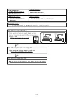
(3). ANTI-FREEZING CONTROL (Cooling mode)
The compressor frequency decreases on cooling mode when the indoor heat exchanger
temperature sensor detects the temperature lower than 37.4°F (3°C).
Then, the anti-freezing control is released when it becomes higher than 42.8°F (6°C).
(Fig 7 : Anti-freezing Protection Operation / Release Temperature)
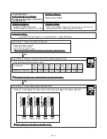
(4). COOLING PRESSURE OVER RISE PROTECTION
When the outdoor unit heat exchange sensor temperature rises to
158.9°F (70.5°C)
or greater,
the compressor is stopped and error display is indicated.
Indoor heat exchange
temperature
37.4°F
(3°C)
42.8°F
(6°C)
46.4°F
(8°C)
The compressor frequency is
decreased 10Hz every 120 seconds.
Compressor OFF : Hold
Compressor ON : Release of protection
Hold
Release of protection
01-21
Summary of Contents for Inverter Halcyon ASU12RMLQ
Page 3: ...1 DESCRIPTION OF EACH CONTROL OPERATION R410A WALL MOUNTED DUCT CASSETTE type INVERTER MULTI ...
Page 26: ...2 TROUBLE SHOOTING R410A WALL MOUNTED DUCT CASSETTE type INVERTER MULTI ...
Page 76: ...3 REPLACEMENT PARTS R410A WALL MOUNTED DUCT CASSETTE type INVERTER MULTI ...
Page 77: ...REPLACEMENT PARTS 03 01 Models ASU9RMLQ ASU12RMLQ ASU18RMLQ INVERTER ...
Page 78: ...REPLACEMENT PARTS 03 02 Models ASU9RMLQ ASU12RMLQ ASU18RMLQ ...
Page 79: ...Model ARU9RML 03 03 REPLACEMENT PARTS ...
Page 80: ...Model ARU9RML 03 04 REPLACEMENT PARTS ...
Page 81: ...Models ARU12RML ARU18RML 03 05 REPLACEMENT PARTS ...
Page 82: ...Models ARU12RML ARU18RML 03 06 REPLACEMENT PARTS ...
Page 83: ...Models ARU9RML ARU12RML ARU18RML 03 07 REPLACEMENT PARTS ...
Page 84: ...40 Models AUU9RML AUU12RML AUU18RML REPLACEMENT PARTS ...
Page 85: ...41 Models AUU9RML AUU12RML AUU18RML CONTROL UNIT REPLACEMENT PARTS ...
Page 86: ...38 CASSETTE TYPE DECORATION PANEL UTG UFUB W REPLACEMENT PARTS ...
Page 88: ...REPLACEMENT PARTS 03 08 Model AOU24RML AOU24RML1 ...
Page 89: ...REPLACEMENT PARTS 03 09 Model AOU24RML AOU24RML1 ...
Page 90: ...REPLACEMENT PARTS 03 10 Model AOU24RML AOU24RML1 ...
Page 92: ...REPLACEMENT PARTS 03 12 Model AOU36RML AOU36RML1 ...
Page 93: ...REPLACEMENT PARTS 03 13 Model AOU36RML AOU36RML1 ...
Page 94: ...REPLACEMENT PARTS 03 14 Model AOU36RML AOU36RML1 ...
Page 141: ...4 APPENDING DATA R410A WALL MOUNTED DUCT CASSETTE type INVERTER MULTI 1 PT CHART ...
Page 145: ...1116 Suenaga Takatsu ku Kawasaki 213 8502 Japan GS06082006 JUN 2006 Printed in Japan ...


