2. AUTO CHANGEOVER OPERATION
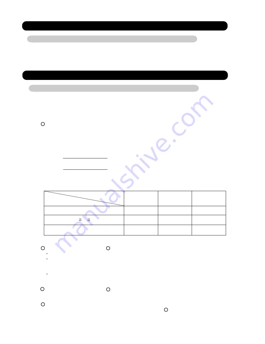
When the air conditioner is set to the AUTO mode by remote control, operation starts in the optimum
mode from among the HEATING, COOLING, DRY and MONITORING modes. During operation, the
optimum mode is automatically switched in accordance with temperature changes. The temperature
can be set between 64°F(18°C) and 88°F(30°C) in 2°F(1°C) steps.
.When operation starts, only the indoor and outdoor fans are operated for 1 minute. After 1 minute,
the room temperature and outside air temperature are sensed and the operation mode is
selected in accordance with the table below.
C zone
90°F(32°C)
B zone
32°F(0°C)
A zone
( Table.1 Operation mode selection table)
Outside air temperature (TO)
Room temperature (TB)
A zone
B zone
C zone
TB > TS+4°F(2°C)
Monitoring
Cooling
(automatic dry)
Cooling
(automatic dry)
TS+4°F(2°C)
TB
TS - 4°F(2°C)
Monitoring
Monitoring
Monitoring
TB TS- 4°F(2°C)
Heating
Heating
Monitoring
.When COOING was selected at
, the air conditioner operates as follow:
The same operation as COOLING OPERATION of item 1 above is performed.
When the room temperature has remained at (set temperature -2°F(1°C)) for 8 minutes, operation is
automatically switched to DRY and the same operation as DRY OPERATION of item 3 above
is performed.
If the room temperature reaches (set tempe4°F(2°C) during DRY operation, operation returns to
COOLING operation.
.When HEATING was selected at
, the same operation as HEATING OPERATION of item 2
above is performed.
When the compressor was stopped for 6 consecutive minutes by the temperature control function
after the COOLING or HEATING operation mode was selected at
above, operation is switched
to MONITORING and the operation mode is selected again.
1
<
1
2
3
1
4
1
( Fig.1 : Outside air temperature zone selection )
01-01
1.
CAPACITY CONTROL
1-1 COOLING, HEATING, DRY CAPACITY CONTROL
Compressor frequency decides by capacity of an indoor unit, operation number of an indoor unit,
set temperature, room temperature and outside temperature.
2-1 For AS, AU type
Summary of Contents for Inverter Halcyon ASU12RMLQ
Page 3: ...1 DESCRIPTION OF EACH CONTROL OPERATION R410A WALL MOUNTED DUCT CASSETTE type INVERTER MULTI ...
Page 26: ...2 TROUBLE SHOOTING R410A WALL MOUNTED DUCT CASSETTE type INVERTER MULTI ...
Page 76: ...3 REPLACEMENT PARTS R410A WALL MOUNTED DUCT CASSETTE type INVERTER MULTI ...
Page 77: ...REPLACEMENT PARTS 03 01 Models ASU9RMLQ ASU12RMLQ ASU18RMLQ INVERTER ...
Page 78: ...REPLACEMENT PARTS 03 02 Models ASU9RMLQ ASU12RMLQ ASU18RMLQ ...
Page 79: ...Model ARU9RML 03 03 REPLACEMENT PARTS ...
Page 80: ...Model ARU9RML 03 04 REPLACEMENT PARTS ...
Page 81: ...Models ARU12RML ARU18RML 03 05 REPLACEMENT PARTS ...
Page 82: ...Models ARU12RML ARU18RML 03 06 REPLACEMENT PARTS ...
Page 83: ...Models ARU9RML ARU12RML ARU18RML 03 07 REPLACEMENT PARTS ...
Page 84: ...40 Models AUU9RML AUU12RML AUU18RML REPLACEMENT PARTS ...
Page 85: ...41 Models AUU9RML AUU12RML AUU18RML CONTROL UNIT REPLACEMENT PARTS ...
Page 86: ...38 CASSETTE TYPE DECORATION PANEL UTG UFUB W REPLACEMENT PARTS ...
Page 88: ...REPLACEMENT PARTS 03 08 Model AOU24RML AOU24RML1 ...
Page 89: ...REPLACEMENT PARTS 03 09 Model AOU24RML AOU24RML1 ...
Page 90: ...REPLACEMENT PARTS 03 10 Model AOU24RML AOU24RML1 ...
Page 92: ...REPLACEMENT PARTS 03 12 Model AOU36RML AOU36RML1 ...
Page 93: ...REPLACEMENT PARTS 03 13 Model AOU36RML AOU36RML1 ...
Page 94: ...REPLACEMENT PARTS 03 14 Model AOU36RML AOU36RML1 ...
Page 141: ...4 APPENDING DATA R410A WALL MOUNTED DUCT CASSETTE type INVERTER MULTI 1 PT CHART ...
Page 145: ...1116 Suenaga Takatsu ku Kawasaki 213 8502 Japan GS06082006 JUN 2006 Printed in Japan ...


