Quick Installation Guide
Fujitsu Technology Solutions GmbH, User Documentation, 33106 Paderborn, Germany • Email - manuals@ts.fujitsu.com
l
Online - http://ts.fujitsu.com/support
All hardware and software names used are trademarks of their respective manufacturers.
590-1057-640A
installation
4
KVM s4 Switch
KVM s4-0812
|
KVM s4-1622
|
KVM s4-3242
The following instructions will help you install
and use your switch easily.
Should you require further assistance, please
consult your installer/user guide.
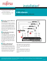
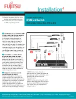
1
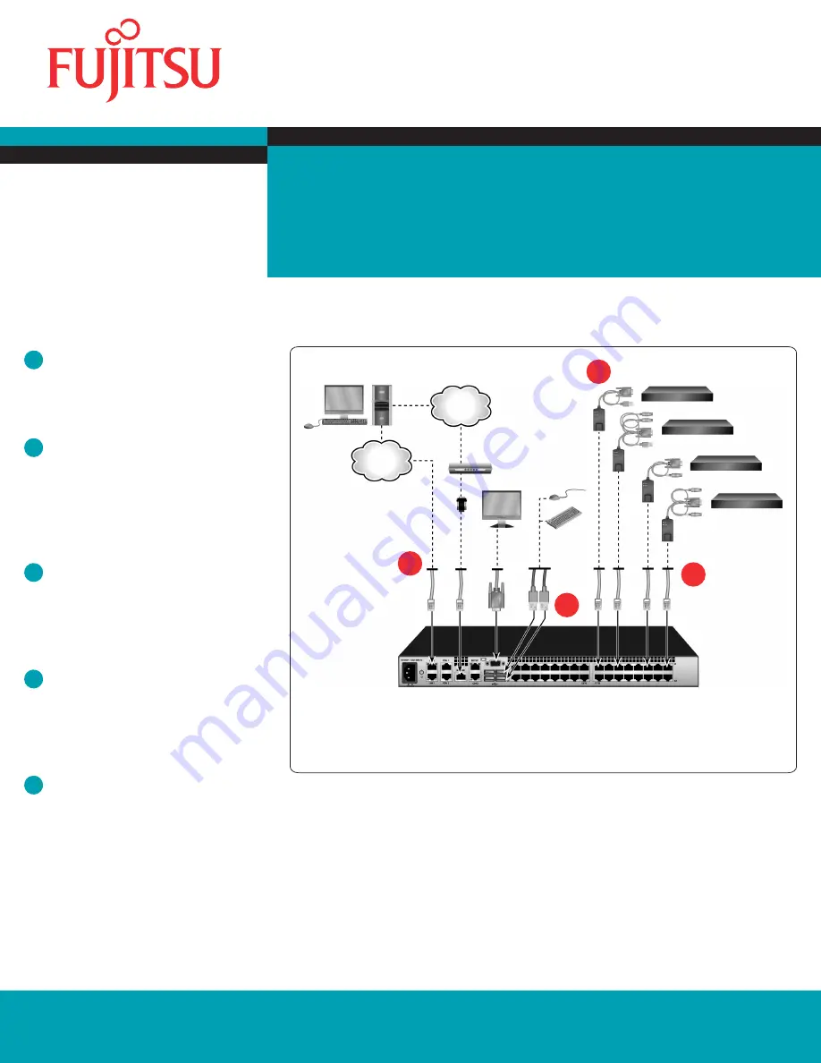
Connecting the local port
Connect your VGA monitor and USB keyboard and
mouse cables into the appropriate ports on the KVM
s4 switch.
2
Connecting a CAT 5 adapter cable to
the KVM s4 switch
Connect one end of a CAT 5 cable (4-pair, up to 150 ft/45 m)
into an available numbered port on the rear of
your switch. Connect the other end into the RJ-45
connector of the CAT 5 adapter cable.
3
Connecting a target device to a CAT
5 adapter cable
Connect a CAT 5 adapter cable into the appropriate
port on the back of a target device. Repeat steps 2
and 3 for all target devices you want to connect.
4
Connecting network users
Connect a customer supplied CAT 5 cable from the
Ethernet network into a LAN port on the back of
the switch. Network users will access the switch
through this port.
5
Connecting to an external modem
(optional)
The switch may also be accessed using an ITU V.92,
V.90 or V.24-compatible modem. Connect one end of
a CAT 5 cable into the MODEM port on the switch.
Connect the other end into the CAT 5 to DB-9 (male)
adapter, which then connects into the appropriate
port on the back of the modem.
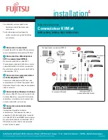
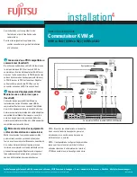
KVM s4 switch configuration
Telephone
network
Target
devices
2
1
KVM s4 Switch
(KVM s4-3242 shown)
Ethernet
Modem
CAT 5
Adapters
3
4
Local USB Connections


