background image

Two

S t a r t i n g   Y o u r   L i f e B o o k   C   S e r i e s

L i f e B o o k   C   S e r i e s   f r o m   F u j i t s u

15

You 

cannot

use your notebook until this

Condition of Use process is completed. The
bottom of each screen has a

<Back 

button, a

Next> 

Button and a

Cancel 

button which

are activated by the integrated ErgoTrac cursor
control and button click. The

<Back 

button

will return you to the previous screen. The

Next> 

button activates any choices or 

information you have entered and takes you on
to the next screen. The

Cancel 

button allows

you to stop the setup process.

If you stop the process your notebook will 
start up at the beginning of the Windows 98
Setup Wizard.

The screens you will be required to respond to
are described with the required action.

User Information

Fill in your name and your company name as
you want the software licensed. To step from the
name field to the company field press the 

Tab

key. When the information has been entered click
on the

Next> 

button. You will not be allowed

to continue until you make an entry.

License Agreement

Read the license agreement carefully. You can
scroll through the text using the integrated
ErgoTrac or TouchPad pointing device to acti-
vate the scroll bar or use the up arrow 

Õ

and

down arrow 

Ô 

keys to move up and down the

text one line at a time, or use the 

Page Up

and

Page Down

keys to move the text one screen at

a time. When you finish reading you must
accept or reject the terms of the agreement 
and then click on the

Next> 

button.

Product Key

Look in the box that your notebook came in
and you will find a Windows 98 Certificate of
Authenticity shrink wrapped with the Windows
98 Users manual. On the certificate you will
find a bar-code with a number above it. This is
your product key and the number you should
enter on the Product Key screen. When you
have entered the number exactly as shown then
click on the

Next> 

button.

Start Wizard

The Start Wizard screen will appear when you
have entered a valid product key. When you
click on the Finish button the display will flash
various screens as the system identifies what
hardware is installed.

Time Zone

When your notebook has completely identified
all of the installed hardware, it will display a
dialog box for entering which time zone you
wish to set the clock to.

P O I N T

If you reject the terms of the license
agreement you will be asked to review
the license agreement for information on
returning Windows 98 or to shut down
your notebook.

Summary of Contents for Lifebook C352

Page 1: ...ate Software Inc LapLink is a registered trademark of Traveling Software Inc All other trademarks mentioned herein are the property of their respective owners Copyright 1999 Fujitsu PC Corporation All rights reserved No part of this publication may be copied reproduced or translated without prior written consent of Fujitsu PC Corporation No part of this publication may be stored or transmitted in ...

Page 2: ...Ns contact your local telephone company If this equipment causes harm to the telephone net work your telephone company may discontinue your service temporarily If possible they will notify you in advance If advance notice is not practical they will notify you as soon as possible You will also be advised of your right to file a complaint with the FCC This fax modem also complies with fax branding r...

Page 3: ...ique de la class B respecte toutes les exigence du Réglement sur le matérial brouilleur du Canada Notice to Users of the Canadian Telephone Network The Canadian Industry Canada label identifies certi fied equipment This certification means that the equipment meets certain telecommunications net work protective operational and safety requirements The Department does not guarantee the equipment will...

Page 4: ... par un service de maintenance agréé au Canada Toute réparation ou modification qui n est pas expressément approuvée par Fujitsu PC Corp C A U T I O N For safety users should ensure that the electrical ground of the power utility the telephone lines and the metallic water pipes are connected together Users should NOT attempt to make such connections themselves but should contact the appropriate el...

Page 5: ...n WARNING CMOS and NiCAD batteries may explode if mistreated Do not recharge disassemble or dispose of in fire A V E R T I S S E M E N T Pour assurer la sécurité les utilisateurs doivent vérifier que la prise de terre du service d électricité les lignes télphoniques et les conduites d eau métalliques sont connectées ensemble Les utilisateurs NE doivent PAS tenter d établir ces connexions eux mêmes...

Page 6: ...T a b l e o f C o n t e n t s ...

Page 7: ...r Operating System and Application Software 17 SECTION THREE USING YOUR LIFEBOOK C SERIES FROM FUJITSU Power Button 20 Restarting the System 21 Status Indicator Panel 22 Batteries 26 Integrated ErgoTrac Pointing Device 29 Using the Keyboard 31 Volume Control 33 Floppy Disk Drive 33 CD ROM Drive 35 Hard Drive 36 Internal Modem 37 Power Management 38 Data Security 43 Pre installed Software 44 SECTIO...

Page 8: ...ices 110 Microphone 110 Stereo Line In Devices 110 Headphones 110 Telephone Lines 111 Mouse Keyboard or Keypad 111 External Monitor 111 Theft Prevention Lock 112 Memory Upgrade Module 112 SECTION SIX TROUBLESHOOTING Identifying the Problem 118 Specific Problems 119 Power On Self Test Messages 138 Emergency CD ROM Tray Release 141 Modem Setup and Commands 141 Recovery CD ROM 142 SECTION SEVEN CARE ...

Page 9: ...LifeBook C Series from Fujitsu P r e f a c e ...

Page 10: ...l interface that enables it to support a variety of optional features and software Figure P 1 CONVENTIONS USED IN THE GUIDE Screen examples in this manual are intended as examples only and screen and file names may differ in actual use Messages displayed by the LifeBook C Series appear in Courier type Example Shutdown the computer Keyboard keys are shown in boldface Helvetica type Example Fn F1 Es...

Page 11: ...L i f e B o o k C S e r i e s f r o m F u j i t s u L i f e B o o k C S e r i e s f r o m F u j i t s u vii Figure P 1 LifeBook C Series with Samples of Fujitsu and Third Party Options and Accessories ...

Page 12: ...es S e c t i o n O n e Unpacking 2 Overview of LifeBook C Series Features 3 Component Identification 5 Top and Front Components 6 Left side Panel Components 7 Right side Panel Components 7 Rear Panel Components 8 Bottom Components 9 ...

Page 13: ...tsu Figure 1 1 Product Registration card Lithium ion battery Already installed in the battery bay of your notebook AC adapter with AC power cord located in the Accessories box Figure 1 2 Phone Modem RJ 11 telephone cable located in the Accessories box Getting Started Guide Accessories Catalog User s Guide Microsoft Windows 98 Guide Microsoft Works Guide International Limited Warranty Brochure Reco...

Page 14: ...leration Built in stereo speakers Built in mono microphone Stereo line in jack Stereo headphone jack Microphone jack Combination PC card slot accommodates 2 Type II or 1 Type III Cards Integrated ErgoTrac pointing device for superb cursor control and comfort External monitor support with simultaneous display capabilities Full size keyboard with three dedicated Windows keys Hot swappable PS 2 port ...

Page 15: ...uding word processing spreadsheets and databases Quicken Basic 99 for money management PC Doctor for system diagnostics PMSet 98 for system power management McAfee VirusScan for virus protection Adobe Acrobat Reader ESS AudioRack for playback of Audio CD and other Audio Controls P O I N T This unit does not come pre installed with the Windows 95 or Windows NT operating systems Windows 98 is the on...

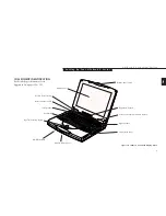
Page 16: ...h Display Open Display Panel Status Indicator Panel Keyboard ErgoTrac Pointing Device CD ROM Drive Closed Cover Switch Built in Microphone Display Panel Latch COMPONENT IDENTIFICATION For detailed specifications refer to Appendix A on pages 150 153 Brightness Control Power and Suspend Resume Button Floppy Disk Drive Left Speaker Right Speaker ...

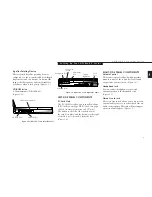
Page 17: ...ivity PC Card activity CapsLock NumLk and Scr Lk Figure 1 3 Power and Suspend Resume Button The Power button allows you to power on your notebook suspend notebook activity without powering off resume your notebook from suspend mode and power off your notebook This multi function button acts as both the suspend resume control and the power switch See page 20 for more information on the power button...

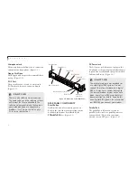
Page 18: ...lots locks the card s in place and the buttons to the right of the slots eject the card s from the slots Figure 1 4 RIGHT SIDE PANEL COMPONENTS Volume Control The volume control is a knob which provides manual control of the sound level of all audio output from your notebook Figure 1 5 Headphone Jack You can connect headphones or powered external speakers to the headphone jack Figure 1 5 Stereo Li...

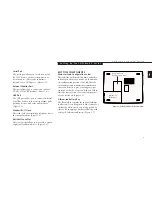
Page 19: ... 5 PS 2 Port The port allows you to connect an external PS 2 keyboard mouse or numeric keypad Figure 1 5 REAR PANEL COMPONENTS Reset Button The Reset button is for restarting your note book in the event that your operating system has halted and cannot be restarted by the CTRL ALT DEL keys Figure 1 6 C A U T I O N There are also software volume controls The knob setting and the software settings wi...

Page 20: ...tored over a long period of time or for swapping a discharged battery with a charged Lithium ion Battery Figure 1 7 Serial Port The serial port allows you to connect serial RS 232C devices such as serial printers or serial scanners This is also sometimes referred to as a COM port Figure 1 6 External Monitor Port This port allows you to connect an external VGA or SVGA CRT monitor Figure 1 6 USB Por...

Page 21: ...Book C Series from Fujitsu S e c t i o n T w o Power Sources 12 Display Panel 13 Starting your LifeBook for the First Time 13 Registering your LifeBook 16 Learning About Your Operating System and Application Software 17 ...

Page 22: ... Connect the Optional Auto airline Adapter 1 Plug the DC Output cable into the DC Power jack on the rear panel of your notebook 2 Plug the auto airline adapter plug into the cigarette lighter or accessory plug of a car or other vehicle with the ignition key in the On or the Accessories position or into the DC Power jack on an airplane seat To Switch From AC Adapter Power To Battery Power 1 Be sure...

Page 23: ...battery will discharge For maximum battery life make sure that the brightness is set as low as possible STARTING YOUR LIFEBOOK FOR THE FIRST TIME Power On The Power Button is located above your key board to the right of the Status Indicator Panel This button is always used to Power On your notebook from its Off state Once you have connected your AC adapter or have charged your internal Lithium ion...

Page 24: ...ndition of use process you must press the F2 key while the Fujitsu logo is still visible If you press the Esc key while the Fujitsu logo is still present you will get a dialog box which will allow you to select which drive is to be used for finding the operating system If you turn off the power without using the on screen Cancel button you will get an error message when you start your notebook aga...

Page 25: ...ng the integrated ErgoTrac or TouchPad pointing device to acti vate the scroll bar or use the up arrow Õ and down arrow Ô keys to move up and down the text one line at a time or use the Page Up and Page Down keys to move the text one screen at a time When you finish reading you must accept or reject the terms of the agreement and then click on the Next button Product Key Look in the box that your ...

Page 26: ... wish to select a printer click on the Cancel button If you do wish to select a printer click on the Next button and answer the questions Welcome to Windows 98 When you boot into Windows 98 for the first time you will see a Welcome to Windows 98 dialog box with several options Select the first option Register Now to register your LifeBook C Series notebook P O I N T You will find a Emergency Recov...

Page 27: ...tware are available online See the help screens of your pre installed software We recommend that you review the on line documentation for general information on the use of these applications and to get a basic understanding of what is covered and how it is organized should questions arise as you use the applications Links to Fujitsu On line You can go directly to the Fujitsu Accessories catalog fo...

Page 28: ...n 20 Restarting the System 21 Status Indicator Panel 22 Batteries 26 Integrated ErgoTrac Pointing Device 29 Using the Keyboard 31 Volume Control 33 Floppy Disk Drive 33 CD ROM Drive 35 Hard Drive 36 Internal Modem 37 Power Management 38 Data Security 43 Pre installed Software 44 ...

Page 29: ...Go to the Start button menu Power Off Before turning off the power by choosing Shut Down from the Windows 98 Start menu or pressing the power button check that the Hard Drive CD ROM PC Card and the Floppy Disk Drive Access indicators are all Off See Figure 3 3 page 22 If you turn off the power while accessing a disk or PC Card there is a risk of loss of data To ensure that your notebook shuts down...

Page 30: ...O N Turning off the power without exiting Windows 98 may cause an error when you start the next time Turning the power to On when it has been Off for less than 10 seconds may also cause an error when you start the next time Figure 3 2 Using the reset button Reset Button The Reset button is located on the rear panel to the left of the DC Power jack This hardware reset button should only be used whe...

Page 31: ... is in Suspend mode It goes off when the system has entered Save to Disk mode or has been powered down by Windows 98 or the Power Button AC Adapter Indicator The AC Adapter indicator tells you whether the system is operating on an AC or auto airline adapter or the battery alone The indicator is On when either of the adapters is active and Off when power comes from the battery alone Figure 3 3 Stat...

Page 32: ...n tifier if the battery is charging The Battery Charging indicator flashes if the battery is too hot or too cold to charge Figure 3 3 The Battery Charging indicators operate whether the notebook is Off or On The symbols inside the battery outline of the Battery Level indicator show the power level and condition of that battery Figure 3 4 C A U T I O N A shorted battery is damaged and must be repla...

Page 33: ...nserted in the drive and the tray is closed It will begin playing an audio CD or will start an application if the CD includes an auto run file CD ROM Drive Access Indicator The CD ROM Access indicator tells you that the CD ROM drive is being accessed The CD ROM Access indicator will flash when the software tries to access a CD even if no CD is inserted P O I N T You can disable the CD automatic in...

Page 34: ... you activated it Hard Drive Access Indicator The Hard Drive Access indicator tells you when the internal hard drive is being accessed Floppy Disk Drive Access Indicator The Floppy Disk Drive Access indicator tells you a floppy disk drive is being accessed The Floppy Disk Drive Access indicator will flash when your software tries to access a floppy disk even if no floppy disk is installed PC Card ...

Page 35: ...rences CD ROM drive hard drive and modem usage may also have a significant impact on battery life The battery charging capacity is reduced as the battery ages If your battery is running low quickly you should replace it with a new one When using a high current device such as a modem a LAN card the CD ROM drive or the hard drive frequently Using the AC adapter will conserve your battery when using ...

Page 36: ...ndica tor to the left of the Battery Level indicator is visible on the Status Indicator panel Make sure the percentage charge is shown inside the Battery Level icon Figure 3 4 on page 23 Recharging the Battery If you want to check the condition of the Lithium ion battery check the Battery Level indicator located on the Status Indicator panel This indicator changes as the battery level changes Ther...

Page 37: ...r is turned off by either hardware or software but you will still be able to see the Battery Level indicator flash When the low battery alarm occurs you need to save all your active data and put your notebook into Suspend mode until you can provide a new power source You should provide this power as soon as possible The new power source can be a charged battery or a power adapter either AC or auto...

Page 38: ...up down left and right A light pressure with the tip of your finger is all that is required to operate the ErgoTrac The more pressure you use the faster the cursor will move The second part of the ErgoTrac point ing device the buttons function as mouse buttons and the functions they perform depend on the application you are running Figure 3 5 shows the position of the ErgoTrac pointing device and ...

Page 39: ... 7 Clicking Clicking means pushing and releasing a button To left click move the screen cursor to the item you wish to select press the left pointing device button once and then immediately release it To right click move the mouse cursor to the item you wish to select press the right pointing device button once and then immediately release it Figure 3 6 Double Clicking Double clicking means follow...

Page 40: ...dows keys Numeric Keypad Certain keys on the keyboard perform dual functions as both standard character keys and numeric keypad keys Figure 3 8 highlights these keys To switch into numeric keypad mode press the NumLk Scr Lk while holding down the Shift key You can now enter numer als 0 through 9 perform addition sub traction multiplication or division and enter decimal points using the keys design...

Page 41: ...oggle between video compensa tion and no compensation Video compensa tion controls spacing on the display When it is enabled displays with less than 800 x 600 pixel resolution will still cover the entire screen Pressing F10 while holding down the Fn key allows you to change your selection of where to send your display video Each time you press the combination of keys you will step to the next choi...

Page 42: ...volume which can be set by the other sources For example if the hardware volume control is turned all the way down your software volume C A U T I O N The operating system volume setting sets the maximum volume level of the hardware volume control knob control settings have no effect By the same token if the operating system has the sound turned off adjusting the hardware or other application softw...

Page 43: ...lizing a disk You need to format new 3 5 floppy disks unless you pur chase preformatted disks Use your notebook s operating system software to format a floppy disk Please refer to the operating system manual for step by step instructions To prevent accidental erasure of data stored on a floppy disk slide the write protect tab on the floppy disk to open up the small hole This makes the disk write p...

Page 44: ... disk drive with any liquid metal or other foreign matter inside the floppy disk drive or disk Never store a floppy disk near a magnet or magnetic field Never disassemble or dismantle your floppy disk drive This may cause damage to your system and will void your warranty Loading a CD Make sure there is power to your notebook Push gently but firmly and release the eject button on the front of the C...

Page 45: ...ction see page 24 you will have to start the CD from your desktop as your notebook will not automatically recognize that the CD has been loaded Do not bend CD ROMs or set heavy objects on them Never write on the label surface with a ball point pen pencil or similar device If a CD ROM is subjected to sudden changes in temperature cold to warm condensation may form on the surface Wipe the moisture o...

Page 46: ...See Recovery CD ROM on page 142 for more information Any application software which you have pur chased and installed will have to be re installed from the original source When doing a recovery remember that you must allocate space for the Save to Disk func tion if you have it enabled See Setting Up Your Save to Disk File Allocation on pages 102 103 for more information C A U T I O N The internal ...

Page 47: ...tebook is active but no Access indicators are on and release the button immediately You will hear two short beeps and then your system will enter Suspend mode If your notebook is suspended pushing the Power button will return your notebook to active operation at the point where it went into suspension You can tell whether or not your system is in Suspend mode by looking at the Power indicator See ...

Page 48: ...24 hours or more Pressing the Power button when your system is in the On state Selecting Standby from the Windows Shut Down menu Timing out from lack of activity Battery level reaching the Dead Battery Warning condition Your notebook s system memory typically stores the file s on which you are working the open application s and any other data required to support the operation s in progress When yo...

Page 49: ...s soon as power is returned If your notebook is in Save to Disk mode pushing the Power button will return your notebook to active operation at the point where it went into Save to Disk mode You can tell whether or not your system is in Save to Disk mode by looking at the Power indicator See page 22 If it is visible and not flashing your notebook is fully operational If it is visible and flashing y...

Page 50: ...uspend mode The Save to Disk pop up will appear on your screen simply wait until it has finished and your notebook will go into Save to Disk mode C A U T I O N Be sure you know which settings are active for the Power Button before you use it misuse can result in data loss See the Power Menu of the BIOS setup utility pages 85 92 for more information Customer configured BIOS methods Press the Power ...

Page 51: ... activity keystroke pointer action sound generation video display change modem transmission or reception etc on your notebook for 16 seconds Any activity will cause the normal operation to restart automatically This feature is independent of the Suspend Resume modes This parameter is enabled and disabled in the BIOS setup utility See pages 85 86 Standby Mode Standby mode is one of the power manage...

Page 52: ...use the notebook and you will have to contact your service provider and arrange to have them reset the hardware system password See your software documen tation for what to do if you forget your software security password s C A U T I O N Software security feature passwords may not be the same as the hardware security passwords Be sure you know which features are controlled from software and which ...

Page 53: ...Multi media Software Service and Support Software and Business Software LapLink LapLink by Traveling Software provides direct file transfers to other computers data transfers via internal modem a PC Card modem a serial cable or a parallel cable cables are not included See the LapLink online help screens for operating instructions Located in the Communications Software folder Quicken 99 Basic Quick...

Page 54: ...CD Backlighting control or CPU Clock control these options are not selectable in the Power Control tab of PMSet 98 P O I N T For maximum frequency response and bandwidth leave the graphic equalizer levels at the mid point zero level To customize the frequency response to your personal taste adjust accordingly C A U T I O N The ESS AudioRack volume settings set the maximum volume level of the hardw...

Page 55: ...tting Standard System Parameters 52 Advanced Menu Setting Device Feature Controls 62 Security Menu Setting the Security Features 80 Power Menu Setting Power Management Feature Controls 85 Boot Menu Selecting the Operating System Source 93 Info Menu Displaying Basic System Information 97 Exit Menu Leaving the Setup Utility 99 Setting Up Your Save To Disk File Allocation 102 ...

Page 56: ...ve letters Example A B C D E to identify internal and external devices such as hard drives floppy disk drives CD ROM drives and PC Cards The most com monly assigned drive designators are listed below If you add other devices the drive designators may be different See your operating system manual for setting drive designations Drive Designators A Floppy disk drive Installed inside your notebook B N...

Page 57: ...tility settings if you want to Change the date or time You can also do this without entering the setup utility through your operating system See your operating system manual Change the primary boot device Change the power management parameter settings Can also be changed in the operating system control panel Change a port address or other parameter Change an audio parameter setting Change the sele...

Page 58: ... 138 140 3 If an error message is displayed on the screen and you want to enter the setup utility press the F2 key 4 When the setup utility starts with a fault pre sent the system displays the following message Warning Error message Continue 5 Press any key to enter the setup utility The system will then display the Main Menu with current parameters values Entering the Setup Utility After a Config...

Page 59: ...e Enter key P O I N T Selecting a field causes a help message about that field to be displayed on the right hand side of the screen P O I N T Pressing the Enter key with the highlight on a selection that is not a submenu or auto selection will cause a list of all options for that item to be displayed Pressing the Enter key again will select the highlighted choice 7 Pressing the F9 key resets all i...

Page 60: ...igure 4 1 Main Menu MAIN MENU SETTING STANDARD SYSTEM PARAMETERS The Main Menu allows you to set or view the current system parameters Follow the instruc tions for Navigating Through The Setup Utility to make any changes See page 51 Table 4 1 shows the names of the menu fields for the Main menu all of the options for each field the default settings and a description of the field s function and any...

Page 61: ...te Date is in a month day year numeric format with 2 digits each for month and day and 4 digits for year MM DD YYYY for example 01 01 1999 You may change each segment of the date separately Move between the segments with the Tab key and or Shift Tab keys Legacy Diskette A 1 44 1 25MB 3 5 Primary Master Selects Primary The product of Display the type of device on this ATA ATAPI interface if there i...

Page 62: ...s detected automatically and cannot be changed by the setup utility Extended Memory 31 MB Displays the size of extended memory which is detected automatically and cannot be changed by the setup utility Memory Cache Selects Memory Cache Configures external cache Submenu Language English Japanese English US Menu Field Options Default Description ...

Page 63: ... field the default settings and a description of the field s function and any special information needed to help understand the field s use Note actual hard drive label shown may vary PhoenixBIOS Setup Utility F1 Help ESC Exit Select Item Select Menu Space Enter F9 Setup Defaults F10 Save and Exit Change Values Select Sub Menu Main Item Specific Help User you enter parameters of hard disk drive in...

Page 64: ...r is selected When User is selected you can change the value This field is changed by incrementing pressing the Spacebar or by typing in the number Heads A number between 1 and 16 15 This item appears only when Auto is selected and the type is identified as hard disk or User is selected When User is selected you can change the value This field is changed by incrementing pressing the Spacebar or by...

Page 65: ...be changed when Auto is selected LBA Mode Control Enabled Disabled Enabled Enables or disables logical Block Addressing in place of Cylinder Head Sector addressing This option cannot be changed when Auto is selected Transfer Mode Standard Fast PIO 1 Fast PIO 2 Fast PIO 4 DMA Selects the method for moving data to from the drive Autotype Fast PIO 3 Fast PIO 4 the drive to select the optimum transfer...

Page 66: ...ettings and a description of the field s function and any special information needed to help understand the field s use Note actual hard drive label shown may vary Figure 4 3 Secondary Master Submenu PhoenixBIOS Setup Utility F1 Help ESC Exit Select Item Select Menu Space Enter F9 Setup Defaults F10 Save and Exit Change Values Select Sub Menu Main Item Specific Help User you enter parameters of ha...

Page 67: ...ransfer MAX refers to the size the disk returns when required This option cannot be changed when Auto is selected LBA Mode Control Enabled Disabled Disabled Enables or disables logical Block Addressing in place of Cylinder Head Sector addressing This option cannot be changed when Auto is selected Transfer Mode Standard Fast PIO 1 Fast PIO 2 Standard Selects the method for moving data to from the d...

Page 68: ... for the Memory Cache submenu all the options for each field the default settings and a description of the field s function and any special informa tion needed to help understand the field s use PhoenixBIOS Setup Utility F1 Help ESC Exit Select Item Select Menu Space Enter F9 Setup Defaults F10 Save and Exit Change Values Select Sub Menu Main Advanced Security Power Boot Info Exit Item Specific He...

Page 69: ...o k C S e r i e s L i f e B o o k C S e r i e s f r o m F u j i t s u 61 Four Menu Field Options Default Description L2 Cache Enabled Disabled Enabled Turns L2 Cache on and off Table 4 4 Fields Options and Defaults for the Memory Cache Submenu ...

Page 70: ...annel Select between the display panel and an external CRT display Enable or disable compensation for your display Set PCI parameters Follow the instructions for Navigating Through the Setup Utility to make any changes See page 51 PhoenixBIOS Setup Utility F1 Help ESC Exit Select Item Select Menu Space Enter F9 Setup Defaults F10 Save and Exit Change Values Select Sub Menu Main Advanced Security P...

Page 71: ...ws the user to modify settings for parallel and serial ports the floppy disk controller and the local bus IDE adapter Keyboard Mouse Features When selected opens the Keyboard Mouse Features submenu with Numlock parameters Multimedia Device When selected opens the Multimedia Device Configuration Configuration submenu which allows setting the hardware address and interrupt levels of audio functions ...

Page 72: ...oppy disk controller Enabled Local Bus IDE adapter Both Configure serial port A using options Disabled No configuration Enabled User configuration Auto BIOS or OS chooses configuration I O Device Configuration Figure 4 6 I O Device Configuration Submenu C A U T I O N I O addresses DMA channels and Interrupt levels can be entered in various ways including via the BIOS setup utility the control soft...

Page 73: ...scription of the field s function and any special information needed to help understand the field s use P O I N T All I O addresses in Table 4 6 are in hexadecimal P O I N T To prevent IRQ and address conflicts avoid changing the default settings If you must change the settings you can call 1 800 8FUJITSU for technical assistance C A U T I O N The BIOS will warn you if there is a resource conflict...

Page 74: ...upt IRQ3 IRQ 4 IRQ 10 IRQ 11 IRQ 4 Set the interrupt for serial port A Serial Port B Disabled Enabled Auto Enabled Configures the serial port B using either no configuration Disabled a user defined configuration Enabled or by allowing the BIOS or OS to choose the configuration Auto Mode IrDA FIR FIR Set the mode for serial port B Base I O address 3F8 2F8 3E8 2E8 2E8 Allows user to set the serial p...

Page 75: ...de for the parallel port Bi directional allows two way transfer of information between your notebook and a connected parallel device Output Only Half Duplex allows information to be transferred in only one direction from your notebook to the printer or similar device ECP Mode allows communication with the ECP class of parallel I O devices Base I O address 378 278 3BC 378 Allows user to set the par...

Page 76: ...e Feature submenu the default settings and a description of the field s function and any special information needed to help understand the field s use F1 Help ESC Exit Select Item Select Menu Space Enter F9 Setup Defaults F10 Save and Exit Change Values Select Sub Menu Advanced Security Power Savings Exit Item Specific Help PhoenixBIOS Setup Utility Selects Power on state for Numlock Keyboard Mous...

Page 77: ... when the computer completes booting Hot Plug Disabled Enabled Enabled Enables or disables the Keyboard Mouse Hot Plug functions Internal Pointing Always Enabled Auto Disabled If Always Enabled is selected the internal pointing device is Device Auto Disabled always enabled If Auto Disabled is selected the internal pointing device is disabled when an external pointing device is connected with the P...

Page 78: ...description of the field s function and any special information needed to help understand the field s use F1 Help ESC Exit Select Item Select Menu Space Enter F9 Setup Defaults F10 Save and Exit Change Values Select Sub Menu Main Advanced Security Power Savings Exit Item Specific Help PhoenixBIOS Setup Utility Configure Multimedia devices Multimedia Device Configuration Multimedia device Enabled S...

Page 79: ...0 22F 240 24F 220 22F When Sound is Enabled this option is available allowing the user 260 26F 280 28F to set the base I O address for the sound device FM I O address 388 38B 38C 38F 388 38B When Sound is Enabled this option is available allowing the user 390 393 394 397 to set the base I O address for the FM device Interrupt IRQ 5 IRQ 7 IRQ 9 IRQ 5 When Sound is Enabled this option is available a...

Page 80: ... all of the options for each field the default settings and a description of the field s function and any special information needed to help understand the field s use F1 Help ESC Exit Select Item Select Menu Space Enter F9 Setup Defaults F10 Save and Exit Change Values Select Sub Menu Main Advanced Security Power Savings Exit Item Specific Help Select display terminal Video Features Display Flat ...

Page 81: ... 4 9 Fields Options and Defaults for the Video Features Submenu of the Advanced Menu Menu Field Options Default Description Display Flat Panel CRT Flat Panel Selects where the video signal will be routed Simultaneous Compensation Enabled Disabled Disabled Enables or disables compensation which controls spacing on the display ...

Page 82: ...for the PCI Configuration submenu all the options for each field and a description of the field s function and any special information needed to help understand the field s use F1 Help ESC Exit Select Item Select Menu Space Enter F9 Setup Defaults F10 Save and Exit Change Values Select Sub Menu Main Advanced Security Power Savings Exit Item Specific Help Reserve specific IRQs for use by legacy ISA...

Page 83: ...nterrupt levels for Reservation Submenu legacy ISA devices Table 4 10 Fields Options and Defaults for the PCI Configuration Submenu Exiting from the Advanced Menu When you have finished setting the parameters on the Advanced Menu you can either exit from setup utility or move to another menu If you wish to exit from setup utility press the Esc key to go to the Exit menu If you wish to move to anot...

Page 84: ...e IRQ Reservation submenu of the PCI Configuration submenu all of the options for each field the default settings and a description of the field s function and any special informa tion needed to help understand the field s use Figure 4 11 IRQ Reservation Submenu F1 Help ESC Exit Select Item Select Menu Space Enter F9 Setup Defaults F10 Save and Exit Change Values Select Sub Menu Main Advanced Secu...

Page 85: ...elected the BIOS reserves IRQ 3 for use by legacy ISA devices and does not use it for embedded PCI or ISA devices IRQ 3 is removed from the IRQ bitmap in the PCI IRQ routing table IRQ 4 Available Reserved Available Reserves IRQ 4 IRQ 5 Available Reserved Available Reserves IRQ 5 IRQ 7 Available Reserved Available Reserves IRQ 7 IRQ 9 Available Reserved Available Reserves IRQ 9 IRQ 10 Available Res...

Page 86: ...ription of the field s function and any special information needed to help understand the field s use F1 Help ESC Exit Select Item Select Menu Space Enter F9 Setup Defaults F10 Save and Exit Change Values Select Sub Menu Main Advanced Security Power Savings Exit Item Specific Help Yes clears all DMI event logs at next boot The value is reset to No after clearing logs DMI Event Logging PhoenixBIOS ...

Page 87: ...MI event logs Yes No No A Yes selection causes the event logs to clear at the next boot Once the logs are cleared this automatically sets to No until reset to yes by selecting yes here Event Logging Enabled Disabled Enabled Turns event logging on and off for all DMI events System Boot Event Enabled Disabled Disabled Turns event logging on and off for DMI system boot events Four Table 4 12 Fields o...

Page 88: ...ecial information needed to help understand the field s use The default condition is no pass words required and no write protection F1 Help ESC Exit Select Item Select Menu Space Enter F9 Setup Defaults F10 Save and Exit Change Values Select Sub Menu Main Advanced Security Power Boot Info Exit Item Specific Help Supervisor Password controls access to the setup utility PhoenixBIOS Setup Utility Sup...

Page 89: ...yboard and mouse to be locked out and the warning System Disabled to be displayed If this happens restart the computer by turning off and on the power with the power button and use the correct password on reboot P O I N T If you make an error when re entering the password a Warning will be displayed on the screen To try again press the Enter key and then retype the password Press the Esc key to ab...

Page 90: ... Password field When a Supervisor Password is set it must be used to access the BIOS setup utility Set User Password Enter This field can only be accessed if the Supervisor Password is set Sets changes or cancels the User Password The User Password may be up to eight characters long and is not case sensitive To cancel a password press the Enter key instead of entering characters in the Enter New P...

Page 91: ...d is required Power Management Enabled Disabled Disabled When set to Enabled a password is required upon Resume from Security Suspend or Save to Disk Mode Fixed disk boot sector Normal Write Protect Normal Write protects boot sector on hard disk to protect against viruses Fixed disk security Primary Master Enabled Disabled Disabled When set to Enabled a password User or Supervisor is required to a...

Page 92: ...rating system Exiting from the Security Menu When you have finished setting the parameters on the Security Menu you can either exit from setup utility or move to another menu If you wish to exit from setup utility press the Esc key to go to the Exit Menu If you wish to move to another menu use the cursor keys ...

Page 93: ...ecific Help Select Power Management Mode Choosing modes changes system power management settings Maximum Power Savings conserves the greatest amount of system power while Maximum Performance conserves power but allows greatest system performance To alter these setting choose Customize To turn off power management choose Disable PhoenixBIOS Setup Utility Power Savings Customized Hard Disk Timeout O...

Page 94: ...ose to customize the parameters you will be able to set this yourself The options available vary from Off which has no inactivity shutoff to 20 minutes Video Timeout 2 minutes to Off Sets the length of time without any user input device activity 20 minutes Off before the display is turned off If you choose a factory combina tion of parameters this field will display the setting If you choose to cu...

Page 95: ...mode If you choose a factory combination of parameters this field will display that setting If you choose to customize the parameters you will be able to set this yourself Off has no inactivity suspension Suspend Mode Suspend Save to Disk Suspend Sets the form of suspension state If you choose Suspend you will suspend operation with power to system memory and everything else powered down or in a v...

Page 96: ...om either the Suspend mode or the Save to Disk mode Resume Time 00 00 00 Sets the designated time on a 24 hour clock when the notebook is to automatically resume operation from the Suspend state The format of the clock setting is hours minutes seconds Each segment of the time is set separately either by incrementing or by typing in the numbers You move between the segments with the Tab key or the ...

Page 97: ... I N T When resuming from a Save to Disk suspension there will be a delay while the contents of system memory and operating parameters are loaded from the hard drive C A U T I O N In Save to Disk mode there is no indication on the Status Indicator to let you know you are suspended rather than shut off from the power button ...

Page 98: ...vings Maximum Off Off Off Off 15 Minutes Performance Disabled Off Off Off Off Off Note This configuration is a sample modified profile it does not appear as a default in the BIOS Customized 2 Minutes 1 Minute On 1 Minute 5 Minutes To get even better battery life keep the display and volume settings as low as possible and use the custom setting to set the parameters as shown Table 4 14 Factory Inst...

Page 99: ...he menu fields for the Video Features submenu all of the options for each field the default settings and a description of the field s function and any special information needed to help understand the field s use PhoenixBIOS Setup Utility F1 Help ESC Exit Select Item Select Menu Space Enter F9 Setup Defaults F10 Save and Exit Change Values Select Sub Menu Item Specific Help Set the SUS RES Switch ...

Page 100: ...he Display panel acting as an automatic resume APM CPU Idle Mode Low Power Standard Low Power Sets the CPU speed during Idle mode Serial Mouse Activity Enabled Disabled Disabled Enables and disables having activity on the serial port cause the system to reactivate from inactivity timeouts Table 4 15 Fields Options and Defaults for the Advanced Features Submenu of the Power Menu Exiting from the Po...

Page 101: ...ields for the Boot menu all of the options for each field the default settings and a description of the field s function and any special information needed to help understand the field s use PhoenixBIOS Setup Utility F1 Help ESC Exit Select Item Select Menu Main Advanced Security Power Boot Info Exit Item Specific Help Allows the system to skip certain tests while booting This will decrease the ti...

Page 102: ...wer On Self Test Fewer tests mean faster turn on Boot time Diagnostic Screen Enabled Disabled Disabled Turns on and off display of test results instead of Fujitsu logo screen during Power On Self Test Boot Device Priority Selects the Boot Device This menu allows setting up the source for the operating system Priority submenu Table 4 16 Fields Options and Defaults for the Boot Menu ...

Page 103: ...f the menu fields for the Boot Device Priority submenu a description of the field s function and any special information needed to help understand the field s use PhoenixBIOS Setup Utility F1 Help ESC Exit Select Item Select Menu Main Advanced Security Power Savings Boot Item Specific Help Use or to highlight a device then or space to move it up the list or to move it down the list Press Esc to ex...

Page 104: ... key to change the order number for that source Be sure to save your changed order when you exit the BIOS setup utility 2 Hard Drive 3 ATAPI CD ROM Drive Table 4 17 Fields Options and Defaults for the Boot Device Priority Exiting from Boot Menu When you have finished setting the boot parameters with the Boot menu you can either exit from the setup utility or move to another menu If you wish to exi...

Page 105: ...fault settings and a description of the field s function and any special information needed to help understand the field s use PhoenixBIOS Setup Utility F1 Help ESC Exit Select Item Select Menu Space Change Values Enter Select Sub Menu F9 Setup Defaults F10 Save and Exit Main Advanced Security Power Savings Boot Info Item Specific Help BIOS Version 1 20 BIOS Date 03 10 1999 BIOS Area E800h FFFFh C...

Page 106: ...IOS Area E800h FFFFh CPU Type Pentium II R C360 or Intel R Celeron TM C352 CPU Speed 333 MHz L1 Cache 32 KB L2 Cache 256 KB C360 or 128 KB C352 Total Memory 64 MB C360 or 32 MB C352 On Board 64 MB C360 or 32 MB SDRAM C352 DIMM Not Installed Asset Number None Table 4 18 Fields Options and Defaults for the Info Menu ...

Page 107: ...names of the menu fields for the Exit menu a description of the field s function and any special information needed to help understand the field s use PhoenixBIOS Setup Utility F1 Help ESC Exit Select Item Select Menu Space Change Values Enter Select Sub Menu F9 Setup Defaults F10 Save and Exit Main Advanced Security Power Savings Boot Exit Item Specific Help Exit System Setup and save your change...

Page 108: ...xit Discarding Changes will exit the setup utility with out writing to the BIOS memory When the BIOS recognizes this selection it will load the operating system and begin operation A message setup warning Configuration has not been saved Save before exiting Yes No will be displayed Load Setup Default Selecting Load Setup Default will load the factory preset default values for all setup items then ...

Page 109: ...iguration now Yes No Save Changes Selecting Save Changes will cause the new settings in all menus to be written to the BIOS memory Save Configuration Changes now Yes No When confirmed the setup utility will return to the Exit menu To return to another menu follow the directions in the Navigating Through the Setup Utility section See page 51 Table 4 19 Fields Options and Defaults for the Exit Menu ...

Page 110: ...ave to Disk function when a disk error has occurred 5 Find out how much space is needed to perform the Save to Disk function with Discard Charges Load previous values from CMOS for all setup items To find out how much space is needed to per form the Save to Disk function with the cur rent memory configuration and how much unused space is available on the internal hard drive do the following 1 Rest...

Page 111: ...procedure below Resetting the Save to Disk Parameters 1 From the Shut Down menu please select the restart option 2 When the Fujitsu Logo appears on your screen press F8 immediately before the Windows 98 banner appears on the screen 3 Select 6 Command prompt only then press Enter 4 At the C prompt type cd fujitsu then press Enter 5 At the C fujitsu prompt type phdisk delete file then press Enter 6 ...

Page 112: ...m ion Battery 106 PC Cards 108 Parallel Port Devices 110 Serial Port Devices 110 USB Devices 110 Microphone 110 Stereo Line In Devices 110 Headphones 110 Telephone Lines 111 Mouse Keyboard or Keypad 111 External Monitor 111 Theft Prevention Lock 112 Memory Upgrade Module 112 ...

Page 113: ... Bus device An Modem RJ 11 jack in the back of your notebook allows you to connect a telephone line to the internal modem A serial port in the back of your notebook allows you to connect serial devices such as RS 232C pointing devices or modems A parallel port in the back of your notebook allows you to connect a parallel printer photo or text scanner etc An external monitor port in the back of you...

Page 114: ...you wish to cold swap 2 Close your display and turn your notebook over on a flat surface 3 Detach the cover of the battery bay 4 Slide the battery pack away from the connector 5 Remove the battery from the bay by tilting it upwards and taking it out of the bay Figure 5 1 Replacing the Battery 6 Insert a new battery by placing it in the bay with the connector end up and then lay it flat 7 Slide the...

Page 115: ...disk cards Type II SCSI cards Type II Zoomed Video cards Type II bottom slot only ATA cards Type III Other PC Cards that conform to PCMCIA 2 1 or CardBus standards For further information refer to the instruc tions supplied with your PC Card Caring for PC Cards PC Cards are durable however you must treat them with care The documentation supplied with your PC Card will provide specific infor mation...

Page 116: ... Card in the card slot with the product name label facing up Figure 5 2 4 When the PC Card is fully inserted the eject button will pop out 5 Flip this button toward the front of your notebook to fold it out of the way 6 When the card is installed lock it in place by sliding the Lock button toward the front of your notebook Figure 5 2 Figure 5 2 Installing and Removing a PC Card C A U T I O N Insta...

Page 117: ... the card to be removed and click on the Stop button 4 Verify that the You can safely remove your card message appears 5 Remove the card 6 If the device cannot be removed message appears save all files close all applications and exit Windows 98 then shutoff the power with the power switch See Power Off on pages 20 21 7 Remove the card C A U T I O N If the PC Card has an external connector and cabl...

Page 118: ...licks and latches See Figure 1 6 on page 8 MOUSE KEYBOARD OR KEYPAD Make sure the connector on your device is the correct PS 2 type Align the arrow on the connector to point to the bottom of your note book and push it in until the connector seats A mouse keyboard or keypad may be installed and automatically recognized by your notebook without restarting or changing setups See Figure 1 5 on page 7 ...

Page 119: ...ou may add modules of different capacity SDRAM modules are required C A U T I O N Never remove screws except the ones specifically shown in the directions for installing and removing the memory upgrade module Figure 5 3 Opening the Memory Upgrade Compartment THEFT PREVENTION LOCK A physical security system lock can be installed on the left rear panel of your notebook See Figure 1 6 on page 8 for t...

Page 120: ... into the connector 6 Press the memory upgrade module down into the compartment until it lodges under the retaining clip You will hear a click when it is properly in place 7 Close the keyboard making sure that the tabs at the back seat properly into their slots until flush with your notebook Figure 5 5 8 Replace the screws and the keyboard lock covers To Install a Memory Upgrade Module 1 Shut Down...

Page 121: ... and close all files and turn power off to your note book See Power Off on pages 20 21 Checking the Computer Recognition of New Memory Capacity When you have changed system memory capacity by adding or removing a memory upgrade module be sure to check that your notebook has recognized all of the memory You can check memory capacity by looking at the Main menu of the setup utility 1 Turn on power u...

Page 122: ... for Total RAM System Extended Installed Memory Memory 32 MB 640 K 31M 48 MB 640 K 47M 64 MB 640 K 63M 96 MB 640 K 95M 128MB 640 K 127M If the total memory displayed is not what you believe it should be check that your memory upgrade module is properly installed If it is properly installed and the capacity is not correctly recognized see the Troubleshooting Section starting on page 118 ...

Page 123: ...u b l e s h o o t i n g S e c t i o n S i x Identifying the Problem 118 Specific Problems 119 Power On Self Test Messages 138 Emergency CD ROM Tray Release 141 Modem Setup and Commands 141 Recovery CD ROM 142 ...

Page 124: ...l connectors are plugged in properly You can also disconnect such devices thus eliminating them as possible causes of failure 4 Go through the boot sequence See Section 2 pages 14 15 5 If the problem has not been resolved refer to the problem guide table which follows for more detailed troubleshooting information See page 119 C A U T I O N Do not return a failed notebook to your supplier until you...

Page 125: ...ded primarily to help your Fujitsu support representative better serve you User Problem Guides When you have problems with your notebook try to find the symptoms under the Problem column of the table for the feature giving you difficulty You will find a description of common causes for that symptom under the column Possible Cause and what if anything you can do to correct the condition under Possi...

Page 126: ...tility Multimedia Device Configuration submenu of the Advanced menu to the default values See pages 70 71 5 Software driver is not configured correctly 5 Refer to your application and operating system documentation for help CD ROM Drive Problems Notebook fails to recognize CD ROM 1 Shipping card is still in the CD ROM drive tray 1 Remove shipping card and replace CD in tray 2 CD ROM is installed w...

Page 127: ...g system is booted from a CD ROM drive designations are automatically adjusted See Boot Options submenu on pages 95 96 7 Windows CD auto insertion function 7 Start the CD from the desktop or is disabled application software or re enable the WindowsCD auto insertion function See CD ROM Access Indicator on pages 22 24 for more information The CD ROM Access indicator on the Status 1 The Windows CD au...

Page 128: ...d See pages 34 35 2 Floppy disk is not loaded correctly 2 Eject floppy disk check orientation and re insert See Floppy Disk Drive on pages 34 35 3 BIOS setup utility has Diskette 3 Revise the setup utility Main menu settings Controller Disabled See Main Menu on pages 52 54 4 Security is set to protect access to floppy 4 Verify your password and security settings disk data shows as 5 1 4 A Security...

Page 129: ...n use by the operating system When the used to start the notebook operating system is booted from a CD ROM drive designations are automatically adjusted See Primary Master Submenu on pages 55 57 3 Security is set so operating system can not 3 Verify your password and security settings be started without a password See Security menu on pages 80 84 Keyboard or Mouse Problems The built in keyboard do...

Page 130: ...o be locking up the system with the correct software driver for that device documentation and activate the proper driver 2 Your system has crashed 2 Restart your system using the reset button on the rear panel See Reset button on page 21 Memory Problems Your power on screen or Main menu of the 1 Your memory upgrade module is not 1 Remove and re install your memory BIOS setup utility information do...

Page 131: ...ly 2 The device may have been installed with an 2 Close your application and restart application running and your notebook your notebook doesn t know it s there 3 Your software may not have the correct 3 See your software documentation and software driver active activate the correct driver 4 You may have the wrong I O address 4 See your device documentation and selected for your device software do...

Page 132: ... running and your notebook restart your notebook doesn t know it s there 3 Your software may not have the correct 3 See your software documentation software driver active and activate the correct driver 4 You may have the wrong I O address 4 See your PC Card documentation to selected for your PC Card device determine the required I O address 5 Your PC Card device and another device are 5 Check all...

Page 133: ... panel to determine the presence and condition of the battery See pages 22 23 Install the battery if it is not installed or a Power adapter if all batteries are dead or unavailable See pages 107 108 and 12 13 2 The battery is installed but is 2 When the battery is dead there will be a completely discharged and the Power beep when the power is turned on and adapter AC or auto airline is not the not...

Page 134: ...y and adapter See Figures 3 3 and 3 4 on pages 22 23 Move the AC cord to a different outlet check for a line switch or tripped circuit breaker for the AC outlet if you are using an auto airline adapter in a car make sure the ignition switch is in the On or Accessories position 4 The battery is installed but is 4 When the battery is dead there will be completely discharged and the Power a beep when...

Page 135: ...battery is installed but is faulty 6 Use the Status Indicator panel to verify and there is no Power adapter AC or auto the presence and condition of the battery airline installed See Figure 3 3 on page 22 If a battery is indicating a short remove that battery and operate from another power source or replace that battery 7 The battery is low 7 If the battery is dead there will be a beep when the po...

Page 136: ...to better suit your operation needs See Power menu on pages 85 87 2 You are operating on battery only and have 2 Install a Power adapter and then push the ignored a low battery alarm until the batteries Suspend Resume button See Low Battery are all at the dead battery state and your machine State on page 28 has gone into Dead Battery Suspend mode 3 You have a battery failure 3 Verify the condition...

Page 137: ...roperly installed 3 Verify that the battery is properly connected by re installing it 4 Your installed battery is faulty 4 Verify the condition of the battery using the Status Indicator panel Figure 3 3 on page 22 and replace or remove any that is shorted The battery seems to discharge too quickly 1 You are running an application which uses 1 Use a Power adapter for this application a great deal o...

Page 138: ...n page 26 temperature The Charging icon on the Status Indicator panel will flash when the battery is outside its operating range Shutdown and Startup Problems The Power button does not work 1 The Power button is disabled from 1 Enable the button from the setup utility the Advanced submenu of the Power menu See page 91 of the setup utility 2 You did not hold the button in long enough 2 Hold the but...

Page 139: ...page 94 2 You have a secured system requiring a 2 Make sure you have the right password password to load your operating system Enter the setup utility and verify the Security settings and modify them as appro priate See Security Menu on pages 80 84 3 Internal hard drive was not detected 3 Use the BIOS setup utility Main menu Primary Master submenu to try to auto detect the internal hard drive An e...

Page 140: ...ideo Problems The built in display is blank 1 Something is pushing on the Closed 1 Clear the Closed Cover switch when you turn on your notebook Cover switch See Figure 1 3 on page 5 2 The notebook is set for an external 2 Pressing F10 while holding down the Fn key monitor only allows you to change your selection of where to send your display video Each time you press the combination of keys you wi...

Page 141: ...erate Contact your support representative The display goes blank by itself after you 1 The notebook has gone into Video timeout 1 Use the keyboard or pointer and if have been using it Standby mode Suspend mode or Save to Disk that does not restore operation push the mode because you have not used it for a Suspend Resume button You may want period of time to close your application and go to the set...

Page 142: ...1 Display compression gives a clearer but of your screen and is surrounded by a dark band support 800 x 600 pixel resolution display smaller display for applications that do not and display compression is enabled support 800 x 600 pixel resolution You can fill the screen but have less resolution by changing your display compression setting See Video Features Submenu of the Advanced Menu on pages 7...

Page 143: ...roper driver 4 Your external monitor is not compatible 4 See your monitor documentation and the with your notebook External Monitor Support portions of Appendix A on pages 150 Miscellaneous Problems An error message is displayed on the screen 1 Application software often has its own 1 See your application manual and help during the operation of an application set of error message displays displays...

Page 144: ...d properly If you have an installed memory upgrade module verify that the module is properly installed If it is properly installed you may want to check your Windows Setup to be sure it is not using unavailable memory until you can contact your support representative nnnn Extended RAM Passed Where nnnn is the amount of memory in kilobytes successfully tested Failing Bits nnnn The hex number nnnn i...

Page 145: ... controller error The keyboard con troller test failed You may have to replace your keyboard or keyboard controller but may be able to use an external keyboard until then Contact your support representative Keyboard error Keyboard not working You may have to replace your keyboard or keyboard controller but may be able to use an external keyboard until then Contact your support representative Keybo...

Page 146: ...ed System BIOS copied to shadow RAM System CMOS checksum bad run SETUP BIOS CMOS RAM has been corrupted or modified incorrectly perhaps by an application program that changes data stored in BIOS memory Run Setup and reconfigure the system System RAM Failed at offset nnnn System memory failed at offset nnnn of in the 64k block at which the error was detected This means that there is a fault in your...

Page 147: ...his means an incoming call BUSY NO ANSWER When using the internal modem with applica tions which are not factory installed see the application documentation Figure 6 1 Emergency CD ROM Tray Release MODEM SETUP AND COMMANDS The operating system and application software that is factory installed detects the modem characteristics and provides the necessary com mand strings to operate the modem The in...

Page 148: ...ught it P O I N T It is recommended that you back up all data files prior to performing either of the recovery options RECOVERY CD ROM Included with your notebook in the Accessories box is an Emergency Recovery CD ROM with the following content A backup copy of the software originally installed by Fujitsu on your new Fujitsu LifeBook can only be used on the listed LifeBook models Sets of device dr...

Page 149: ...ee that the Recovery CD is installed in the CD ROM drive and repeat the previous steps starting with 2 If you received a message This program may not be used on your computer you are using the wrong Recovery CD for this model of notebook 6 Read the information displayed on the Welcome screen then Click OK 7 Select one of the two icons displayed in the Emergency Recovery menu and follow the instruc...

Page 150: ...ically to the additional files and utilities that are provided on the Recovery CD for your particular Lifebook model P O I N T As long is there is no boot disk in the CD ROM drive or the floppy disk drive your notebook will boot from the hard drive regardless of the operating system source setting Your notebook now has all of the software installed that was installed when you received it from the ...

Page 151: ...C a r e a n d M a i n t e n a n c e S e c t i o n S e v e n Caring for Your Notebook 146 Increasing Battery Life 147 Caring for Your Batteries 147 ...

Page 152: ...fter the notebook and the battery packs CARING FOR YOUR NOTEBOOK The LifeBook C Series is a durable but sensitive electronic device Treat it with respect and care Make a habit of transporting it in a suitable carrying case Keep it away from food and beverages If you accidentally spill liquid on your notebook 1 Turn it on 2 Position it so that the liquid can run out 3 Let it dry out for 24 hours or...

Page 153: ...mum battery life 5 Put your notebook in Suspend mode when it is turned on and you are not actually using it 6 Limit your CD ROM and modem usage 7 Disable the Windows 98 CD automatic insertion function See page 24 8 Always use fully charged batteries CARING FOR YOUR BATTERIES If your notebook is to be stored for a month or longer turn the machine on and remove the internal Lithium ion battery Store...

Page 154: ... c i f i c a t i o n s a n d G l o s s a r y A p p e n d i c e s Appendix A Specifications 150 Warranty 150 LifeBook C Series Specifications 150 Approvals 153 Popular Accessories 153 Appendix B Glossary 154 ...

Page 155: ...B SDRAM C352 L2 Cache Memory 256KB On die C360 or 128KB On die C352 BIOS Memory 512KB Flash ROM 256 Bytes CMOS RAM with back up battery Video RAM 2MB SDRAM Floppy Disk Drive One 3 5 floppy disk drive which accommo dates a 1 44MB or a 720KB floppy disk Hard Drive C360 C352 One factory installed 4 3GB 2 5 9 5 mm height fixed hard drive unit CD ROM Drive One 24x maximum 5 25 12 7 mm height fixed driv...

Page 156: ...ications One mono microphone jack See Audio specifications One stereo line in jack See Audio specifications Displays Built in color flat panel TFT LCD display with simultaneous display capability C352 Diagonal dimension 12 1 800 x 600 pixel resolution 256K colors SVGA and VGA compatible C360 Diagonal dimension 13 3 1024 x 768 pixel resolution 64k colors XGA SVGA and VGA compatible External Monitor...

Page 157: ... N Actual battery life will vary based on screen brightness applications features power management settings battery conditioning and other customer preferences CD ROM or hard drive usage may also have a significant impact on battery life AC Adapter Autosensing 100 240V AC 44 8W supplying 16V DC to the Notebook Power Management Save to Disk Suspend Idle and Standby power savings modes When the batt...

Page 158: ...nada Certification See statement at the front of this User s Guide POPULAR ACCESSORIES Optional Expansion Memory 16MB 32MB and 64MB SDRAM Modules extend system memory up to 128MB C360 or 96MB C352 installable in a single DIMM dual in line memory module slot in a compartment under the keyboard of the notebook SDRAM Modules are required Fujitsu product numbers 16MB SDRAM FPCEM05 32MB SDRAM FPCEM06 6...

Page 159: ...ion on the configuration and status of the hardware Bit An abbreviation for binary digit A single piece of information which is either a one 1 or a zero 0 bps An abbreviation for bits per second Used to describe data transfer rates Boot To start up a computer and load its operating system from disk ROM or other storage media into RAM Bus An electrical circuit which passes data between the CPU and ...

Page 160: ... Ray Tube A display device which uses a beam of electronic particles striking a lumi nescent screen It produces a visual image by varying the position and intensity of the beam Data The information a system stores and processes DC Direct current A voltage or current that does not fluctuate periodically with time Default Value A preprogrammed value to be used if you fail to set your own DIMM Dual I...

Page 161: ...odel of device in order to produce the desired results from that particular equipment ECP Extended Capability Port A set of standards for high speed data communication and intercon nection between electronic devices ESD Electro Static Discharge The sudden discharge of electricity from a static charge which has built up slowly Example the shock you get from a doorknob on a dry day or the sparks you...

Page 162: ...were the first and latter the most common device connected to parallel ports MB Megabyte Memory A repository for data and applications which is readily accessible to your computer CPU MHz Megahertz MIDI Musical Instrument Digital Interface A stan dard communication protocol for exchange of information between computers and sound producers such as synthesizers Modem A contraction for MOdulator DEMo...

Page 163: ...addressed by the operating system accordingly PCMCIA A trademark of the Personal Computer Memory Card International Association The Personal Computer Memory Card International Association is an organization that sets stan dards for add in cards for personal computers Peripheral Device A piece of equipment which performs a specific function associated with but not integral to a computer Examples a ...

Page 164: ... this refers to returning to active operation after having been in one of the suspension states ROM Read Only Memory A form of memory in which information is stored by physically altering the material Data stored in this way can not be changed by your Computer and does not require power to maintain it SCSI Small Computer Systems Interface pronounced scuzzy An American National Standards Institute ...

Page 165: ... 2 series of personal computers VRAM Video Random Access Memory A memory dedicated to video display data and control Write Protect Prevent alteration of the binary state of all bits in a storage media Example all information on a device such as a floppy diskette a block of space in a storage media such as a partition of a hard drive a file or directory of floppy diskette or hard drive XGA Extended...

Reviews: