background image

Warnings
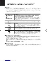
This manual uses a variety of icons as visual marks so that you can use this computer safely and
correctly and avoid damage and danger to yourself and to others.  These icons and their meanings
are as follows. Please learn these icons before reading this manual.  Learning these icons will be
useful for understanding this manual.

Icon

Meaning

 Incorrect handling or ignoring this warning can cause a dangerous
situation that could result in death or severe injury.

Incorrect handling or ignoring this warning can cause a dangerous
situation that could result in moderate or minor injury or could result in
equipment damage.

The symbols below are used together with the icons above to indicate what type of danger or
damage is involved.

Symbol

Meaning

The   symbol indicates a w arning or caution. The symbol inside the 
indicates the concrete nature of the warning. (The example on the left
is a caution for electric shock.)

The circle and slash indicates prohibited behavior.  The symbol inside
the circle indicates the concrete nature of the prohibition. (The
example on the left indicates that disassembly is prohibited.)

The 

 indicates instructions that must be followed.  The symbol inside

indicates the concrete nature of those instructions. (The example on
the left tells you to unplug the power plug from the socket.)

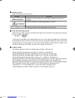
Key notation and operation methods
Explanations of key operations do not show all the characters on the keyboard. Instead they
indicate just the keys necessary to the explanation as follows.
Examples: [Ctrl] key, [Enter] key, 

 ] key

When multiple keys are to be pressed at the same time, this is indicated by connecting them with
[+].
Examples: [Ctrl] + [F3] keys; [Shift] + [ 

 ] key

Screen examples
The screens shown in this manual are examples. Please understand that the file names and
screens you use may be different.

NOTATION IN THIS DOCUMENT

WARNING

CAUTION

00NYX E(Intro)

17/05/2001, 8:41 AM

6

Summary of Contents for LIFEBOOK P1010

Page 1: ...Technologies Corporation Other product names are trademarks or registered trademarks of their respective companies Other products are copyrighted by their companies Copyright 1981 1999 Microsoft Corporation All rights reserved Copyright 1999 Phoenix Technologies Ltd All rights reserved All other products are trademarks or registered trademarks of their respective companies Copyright 2001 Fujitsu L...

Page 2: ...rating of all products plugged into the wall outlet does not exceed 15 amperes 11 Never push objects of any kind into this product through cabinet slots as they may touch dangerous voltage points that could result in a fire or electric shock Never spill liquid of any kind on the product 12 Do not attempt to service this product yourself as opening or removing covers may expose you to dangerous vol...

Page 3: ...ed below To do so would result in your modem being operated in a non compliant manner Call Attempts Retries Applications software shall be configured so that no more than 3 attempts are made to establish a connection to a given number Note if the modem can detect service tones up to 10 attempts can be made If the call sequence is unsuccessful there shall be a delay of at least 30 minutes before at...

Page 4: ...dialing while the New Zealand standard is DTMF tone dialing There is no guarantee that Telecom lines will always continue to support pulse dialing It is strongly recommended that pulse dialing is not used Some parameters required for compliance with Telecom s Telepermit requirements are dependent on the equipment PC associated with this device The associated equipment shall be set to operate withi...

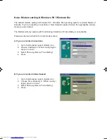
Page 5: ...ate with Tone Dialing Selection of Pulse dialing is not possible Please see below instruction for quick modem setup A If you are located in Australia 1 Go to Control panel select modem icon 2 Choose Australia in What country region are you in now 3 Select Phone system as Tone Dialing 4 Close B If you are located in New Zealand 1 Go to Control panel select modem icon 2 Choose New Zealand in What co...

Page 6: ... indicates the concrete nature of the warning The example on the left is a caution for electric shock The circle and slash indicates prohibited behavior The symbol inside the circle indicates the concrete nature of the prohibition The example on the left indicates that disassembly is prohibited The indicates instructions that must be followed The symbol inside indicates the concrete nature of thos...

Page 7: ... manual as lowercase latin letters but uppercase letters may be used Product names The following product names are abbreviated as follows in this manual Microsoft Windows 98 operating system is written as Windows 98 Microsoftt Millennium Edition operating system is written as Windows Me Microsoft MS DOS operating system Version 6 2 V is written as MS DOS Microsoft Windows operating system Version ...

Page 8: ...d their functions quick point IV operation methods connector box handling and battery operation SECTION 2 This section explains installation of options for this computer SECTION 3 This section explains what to do when trouble occurs with this computer and when messages are displayed Read this section as the necessity arises SECTION 1 SECTION 2 SECTION 3 ...

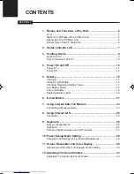
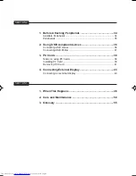
Page 9: ...cking Remaining Battery Power 17 Low Battery Status 18 Notes on Battery 19 Replacing Battery Pack 20 6 E mail Button 21 7 Using Internal Data Fax Modem 23 Connecting a Modular Cable 23 8 Using Internal LAN 25 Connection 25 9 Keyboard 26 Numeric Keypad Mode 26 Keyboard 26 Names of the Main Keys and their Functions 27 10 Power Saving Mode Setting 28 Changing The Settings Using Power Management 28 11...

Page 10: ...B compliant devices 36 Connecting USB mouse 36 Connecting USB Printer 37 3 PC Cards 38 Notes on using PC Cards 38 Installing PC Card 39 Removing PC Card 41 4 Connecting External Display 43 Connecting an external display 43 1 When This Happens 46 2 Care and Maintenance 50 3 Glossary 55 SECTION 3 ...

Page 11: ...basic items for using this computer including the names of the parts and their functions Flat point operation methods floppy disk unit handing and battery operation SECTION SECTION SECTION SECTION SECTION SECTION SECTION SECTION SECTION SECTION 1 1 1 1 1 1 1 1 1 1 ...

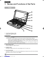
Page 12: ... fact means that the display may contain some unlit or continuously lit dots The color tone of the LCD of this PC may differ from unit to unit Temperature changes and other factors may result in some uneven color tone 2 Status Indicator LCD This LCD displays the status of this PC 3 SUS RES Switch This switch is used to set the PC unit to standby mode or to resume use 4 Cover Close Switch This swit...

Page 13: ...is device 6 Quick Point IV Quick Point IV allows you to control the mouse pointer 7 Speaker This outputs the sound from this PC unit Critical Point Do not put heavy loads on the speaker or you may damage the unit 8 E mail launcher button This button allows you to launch the email application ...

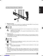
Page 14: ...m accidentally being removed 3 PC Card Slot Insert separately available PC cards here Critical Point Some operating system might call Slot 1 Slot 0 4 DC IN Connector This is the connector to connect the AC adapter supplied to the PC unit 5 Anti theft Lock The Anti theft Lock enables you to connect a separately available cable for theft prevention Critical Point This anti theft lock is compatible w...

Page 15: ...le at stores 3 5 mm mini plug type However some headphones are not compatible and cannot be used Please check whether they can be connected before purchasing CAUTION HEARING LOSS Be careful not to use headphones at excessive volume levels for a long time or they might adversely affect your hearing HEARING LOSS Do not turn the power switch on or off while wearing the headphones or they might advers...

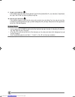
Page 16: ... this connector 7 Communication Connector The internal LAN RJ 45 port is used for an internal Fast Ethernet 10 100 Base T Tx connection IMPORTANT When you connect peripheral devices to each corresponding connector confirm the correct direction of the connector and insert directly into the connector Bottom Side of the PC Main Unit 1 2 3 1 Shutdown Switch This switch is used to forcibly shutdown the...

Page 17: ...e battery is charged And it blinks when battery charge is not in progress because the battery is too hot or too cold 5 Remaining Battery Power Indicator This indicator indicates the remaining battery power 6 Hard Disk Access Indicator This indicator appears when the internal hard disk is accessed See also POINT on the next page 7 PC Card Access Indicator 1 This indicator appears when a PC card is ...

Page 18: ...can set and reset the scroll lock by pressing the Scr Lk key while holding down the Fn key It depends on the application when this indicator appears Critical Point If you operate the SUS RES switch while the hard disk access indicator is showing the data on the hard disk may be corrupted When the PC unit is turned off all of the indicators on the status indicator LCD disappear except during chargi...

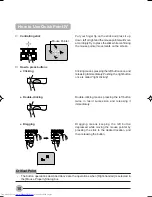
Page 19: ... at the front of the keyboard The stick functions as a ball inside a mouse and moves the mouse pointer around the screen up down left and right as you press it lightly with your finger tip The left button works as the left mouse button and the right button as the right mouse button The functions they perform vary depending on the application you are running The center button is used to scroll the ...

Page 20: ...d succession and releasing it immediately How to press buttons Clicking Double clicking Dragging Clicking means pressing the left button once and releasing it immediately Pushing the right button once is called right clicking Dragging means keeping the left button depressed while moving the mouse pointer by pressing the stick to the desired location and then releasing the button Critical Point The...

Page 21: ...n click on the area within the window that contains the information you want to see then move the stick while keeping the scroll button depressed The stick movements upward downward to right and left allow you to scroll the screen in the corresponding directions ...

Page 22: ...re great power consumption such as continuous use for a long time or communication use Notes on using the PC unit with a battery The battery may not be charged in the following cases Check the remaining power of the battery and recharge it if necessary When you use the PC unit for the first time after purchasing it When the battery has not been charged for a month or more 1 Connect the AC adapter ...

Page 23: ... cannot use this PC unit continuously for more than 24 hours Turn off the power if you are not going to use the PC for a long time Do not press the SUS RES switch down for more than 4 seconds Holding the SUS RES switch down for more than 4 seconds turns off the power and unsaved data may be lost z Status indicator LCD SUS RES switch ...

Page 24: ...n procedure Eject any CD or other media before turning off the power 1 Quit the work you have done Save the data as required before quitting the application 2 Make sure that is not displayed on the status indicator LCD 3 Click on the Start menu button 4 Click on Exit Windows 5 Select Shutdown then click on OK After a while on the status indicator LCD disappears and the system is automatically turn...

Page 25: ... removing peripherals When not using the PC unit for a long time Critical Point If the power is not turned off When the running application becomes inoperative and you cannot turn off the power keep the Ctrl and Alt keys pressed down and press the Del key to restart the application If you cannot restart the application shut down the system forcibly by pressing the shutdown switch on the bottom sid...

Page 26: ...attery power is still 90 or more the unit does not start charging even if the AC adapter is connected Charging starts when the power is 89 or less When the power is turned off the indication on the status indicator LCD disappears soon after charging is complete The battery charging capability deteriorates if the room temperature is too high or too low Battery charging might not begin if the batter...

Page 27: ... status the remaining battery power is about 12 or less blinks This means that the battery is completely exhausted The remaining battery power is 0 Critical Point The remaining battery power indicator may show a different indicator value from the actual remaining battery power depending on the environment of use temperature battery usage and recharging cycle numbers etc because of the characterist...

Page 28: ...on you are running after saving the working data and then shut down the power to the PC Reading and writing processes on the hard disk consumes a large amount of power If you save data on the hard disk when the battery is low always connect the AC adapter If the PC is left in a low battery condition it automatically goes into the standby mode If the system is reading writing on the hard disk or ot...

Page 29: ...reduced as the battery ages If your battery runs low quickly it is a sign that it is getting old Disposing of the battery When you dispose of a battery take measures so as to insulate the battery terminals with tape to prevent short circuiting Also check with your local government authority for details regarding disposal of batteries Prolonging actual battery life Use the power saving function to ...

Page 30: ... may cause an electric shock or a PC failure Critical Point When a new battery pack is required you should purchase the right type Contact your service provider 1 Turn off the power to your PC and disconnect the AC adapter 2 Close the LCD Display and turn the bottom side of your PC up 3 Remove the battery pack Remove the battery pack sliding both of the battery pack locks to unlock it 4 Install a ...

Page 31: ...the clock is displayed When you see this icon you will know that Fujitsu Quick Touch application is active As an E mail application launcher button the Fujitsu Quick Touch applcation is very flexible giving you an options to set for using other E mail application The default setting for the E mail application is Outlook Express We have provided the Fujitsu Quick Touch application that quickly and ...

Page 32: ... Consult your Service provider if you do not know or are unsure of the information requested If Dial Up Click on Dial Up Choose the Dial up configuration as previously set in Dial Up Networking you wish to retrieve mail from Enter the POP3 Server name your account name and password for that account 7 After all the setting are set correctly try to do a testing on the connection by clicking the Test...

Page 33: ... ISDN or it may cause a fire or failure Always connect it via a TA terminal adapter IMPORTANT When your PC is powered on for the first time some settings related to the telephone line are required Check the type of telephone line you are using before setting Connecting a Modular Cable 2 Disconnect your telephone s modular cable from the modular connector of the telephone line Pull it out while pre...

Page 34: ...communication The telephone is not usable with its modular cable disconnected Do not forget to connect it for telephone use after finishing Internet communication If the modular cable is not sufficiently long If the supplied modular cable is too short for your PC environment purchase a new one with the proper length Note on connecting to the Internet for a long time Connecting to the Internet for ...

Page 35: ...f the PC unit and remove the AC adapter and a LAN cable or the thunder may destroy the PC and cause fire CAUTION ELECTRIC SHOCK Do not insert your finger into LAN connector or you may experience electric shock 1 Turn off the power of the PC unit and remove the AC adapter 2 Connect the LAN connector on the PC unit and the network with a LAN cable Connection Critical Point To remove the plug from th...

Page 36: ... called numeric keypad mode The keyboard is switched to numeric keypad mode with Num Lk In numeric keypad mode 1 is displayed on the status indicator LCD The keys surrounded by thick lines in the diagram above become the numeric keypad The numbers input with these keys are printed in front of each key Critical Point When the separately sold numeric keypad is connected if you press Num Lk to put th...

Page 37: ...00 x 600 pixel resolution will still cover the entire screen Fn F6 Pressing F6 repeatedly while holding Fn will lower the brightness of your display Fn F7 Pressing F7 repeatedly while holding Fn will increase the brightness of the display Fn F8 Pressing F8 repeatedly while holding FN will decrease the volume of your LifeBook Fn F9 Pressing F9 repeatedly while holding FN will increase the volume of...

Page 38: ...n the battery runs short the data being generated cannot be saved In addition it may cause the PC to malfunction Low battery status represents a condition where the residual power of the battery is about 12 or less The low battery condition causes the remaining battery power indication on the status indicator LCD to flash regardless of the settings in the Alarm tab Detailed Setting tab You can set...

Page 39: ...mouse pointer to show the hidden part 2Images are displayed using 16 77 million colors by means of the dithering function which shows pseudo colors Critical Point Take one of the following actions to change from the entire screen display to the normal display Press Fn F5 Pressing them again to resume the previous display mode High Color 16 bits displays 65 536 colors and True Color 16 77 million c...

Page 40: ...k on OK The screen displays a dialog box for confirmation of the new settings If this is not the case the settings are automatically changed 4 Click on OK or Yes Click on OK or Yes every time a dialog box prompts you to confirmation This will make the screen settings effective Entire Screen Display Setting The entire screen display mode is activated after you select a resolution other than the ini...

Page 41: ... on the center of the LCD screen after selecting a resolution that is not the default value If the circle is ticked you have large images on the entire LCD screen even after selecting a resolution that is not the default value 6 Click on OK 7 Click on OK Display Properties dialog box is shown on the display 8 Click on OK Critical Point The resolution is defaulted to 1024 x 512 ...

Page 42: ...off the screen shows an indication of Mute The volume level indicator appears only when the Power Management Properties dialog box include the BATTERYAID 2 2 tab Adjusting The Volume Via The Keyboard Adjusting The Volume Via The Volume Control Slider Shown On The Display If the volume level is too high or too low even after adjusting via the keyboard then you should use the volume control slider f...

Page 43: ...SECTION 2 This section explains installation of options for this computer SECTION SECTION SECTION SECTION SECTION SECTION SECTION SECTION SECTION SECTION 2 2 2 2 2 2 2 2 2 2 ...

Page 44: ...34 1 Before Attaching Peripherals SECTION 2 Available Peripherals PC Card FDD Unit USB USB Mouse CCD Camera Printer USB External Display ...

Page 45: ... about Fujitsu genuine optional devices consult with your dealer We cannot guarantee the proper function of this PC when using peripherals from other sources If it becomes necessary to use a peripheral from another source consult with the manufacturer of that product Use peripherals that conform to ACPI standards This PC is set to ACPI mode Power save and other functions may not work correctly if ...

Page 46: ...disable the Quick Point IV see Disabling Quick Point IV Disabling Quick Point IV When you connect a USB mouse to this PC both Quick Point IV and the USB mouse are enabled If you want to disable Quick Point IV when you connect a USB mouse make the following settings 1 With Windows running press the F4 key while pressing down the Fn key Quick Point IV is enabled or disabled each time you press the k...

Page 47: ...nnect the USB cable to the printer For the connection procedures follow the instructions in the manuals of the printer and USB cable 2 Connect the USB cable to the USB connector of the PC unit Align the connectors by matching their shapes and insert the connector of the USB cable straight into the USB connector USB connector 3 Connect the power cable to the printer Refer to the User s Guide of the...

Page 48: ...ch use 12V Notes on using PC Cards Observe the following points when using PC cards to prevent breakdown You should pay attention to the following points when you use PC Cards in order to prevent failures Do not place PC cards in high temperature locations and locations subject to direct sunlight Do not subject PC cards to strong shocks Avoid rubbing PC cards and building up static electricity Do ...

Page 49: ...rocedures of your PC card Installing PC Card A PC card is the same size as a name card and is equipped with peripheral device functions such as a modem This section explains how to install a PC card into your PC CAUTION INJURY Do not put your finger into the PC card slot when you install a PC card or you may be injured Critical Point it may be required to turn off the power of the PC or to install...

Page 50: ...nsert the PC card fully into the PC card slot with the product name label facing up 4 If the PC card is being installed for the first time install any necessary driver Some PC cards require the installation of a driver Check the User s Guide supplied with each PC card and install a driver if required A floppy disk or a CD ROM may be required to install a driver PC card eject button PC card eject b...

Page 51: ...e restart Click on NO 7 Click on Start and Exit Windows to exit Windows 8 Remove the PC card See Steps 4 6 of Removing PC cards Do not put anything heavy on or apply a shock to the connector of the cord connected with the PC card or it may damage the equipment Removing PC Card Here is the explanation of how to remove a PC card Critical Point When you remove a PC card attached with a cable do not p...

Page 52: ...card slot to avoid cutting your fingertips 1 Click on the Eject Hardware icon on the task bar 2 Select the name of the PC card from the Eject hardware dialog box and click on Stop XXXXX XXXXX indicates your PC card name 3 Select the name of the PC card from the Hardware device dialog box and click on Stop XXXXX The PC card stops working 4 Click on OK 6 Remove the PC Card Press the PC card eject bu...

Page 53: ...ction If the PC is used with a wrong connection the PC and or the external display may be damaged 1 Switch the PC power off and disconnect the AC adapter 2 Connect the display cable to the external display connector on the rear side of the PC When viewed from the front the connectors are in a trapezium shape Study the shapes of the connectors and firmly insert the Vga converter cable connector 1 t...

Page 54: ...ears In such cases follow the instruction on the display to install the driver for the external display WARNING Your notebook default screen size resolution is set at 1024 x 512 If you enable your external monitor by pressing Fn F10 you may notice that the screen size and icons are elongated This phenomenon is normal You may choose to set higher or lower resolution of the external monitor to 1024 ...

Page 55: ...3 3 3 3 3 3 3 3 3 3 SECTION SECTION SECTION SECTION SECTION SECTION SECTION SECTION SECTION SECTION SECTION 3 ...

Page 56: ...w LOW BATTERY Connect the AC adaptor When using the computer for the first time after leaving it unused for a long time connect the AC adaptor and switch on the main switch to switch on the power Nothing displayed on the LCD panel Checkpoint Is anything displayed on the status indicator LCD Is displayed on the LCD panel Cause and Solution Connect the AC adaptor and switch on the main switch Displa...

Page 57: ...shes Was the charging stopped midway Cause and Solution Check that the AC adaptor is correctly plugged into the power socket and into the computer If the ambient temperature is high and the battery temperature becomes too high during use the battery protection function may be triggered to stop the charging If the battery temperature falls too low the battery protection function may be triggered to...

Page 58: ...ed accessibility cannot be controlled by this item Set the write protect tab on the floppy disk to the write enable position If it works with a different floppy disk then the problem floppy disk may be damaged LCD panel does not close Checkpoint Is something caught in the LCD panel Cause and Solution Forcing the LCD panel closed can damage it Check for some thing caught in the LCD panel Also a met...

Page 59: ...computer main unit is in operating mode because its CD ROM drive has an electronic lock Check that the personal computer main unit is in operating mode and press the EJECT button If for some reason the CD tray does not come out even when you press the EJECT button insert a clip or something into the hole to the right of the EJECT button and pull the tray out If the tray doesn t still come out clic...

Page 60: ...y out for 24 hours or longer if needed 4 If your notebook will not boot after it has dried out call your support representative Do not use your LifeBook notebook in a wet environment near a bathtub swimming pool Always use the AC adapter and batteries that are approved for your notebook Avoid exposure to sand dust and other environmental hazards Do not expose your LifeBook notebook to direct sunli...

Page 61: ...when you travel If you experience system software problems while travelling you may need it to correct any problems Never put your LifeBook notebook through a metal detector Have your notebook hand inspected by security personnel You can however put your LifeBook notebook through a properly tuned X ray machine To avoid problems place your notebook close to the entrance of the machine and remove it...

Page 62: ...ot locations for more than a day or two Intense heat can shorten battery life Do not leave a battery in storage for longer than 6 months without recharging it Increasing Battery Life Power your LifeBook notebook through the AC or optional auto airline adapter whenever possible If your LifeBook notebook is running on battery power all day connect it to the AC adapater overnight to recharge the batt...

Page 63: ...CD RW CDs DVD CD RW CDs are precision devices and will function reliably if given reasonable care Always store your DVD CD RW CDs in its case when it is not in use Always handle DVD CD RW CDs by the edges and avoid touching the surface Avoid storing any DVD CD RW CDs in extreme temperatures Do not bend DVD CD RW CDs or set heavy objects on them Do not spill liquids on DVD CD RW CDs Do not scratch ...

Page 64: ...Avoid using or storing the drive where it will be subjected to shock or vibration Do not disassemble or dismantle the DVD CD RW D ROM drive PC CARDS Caring for your PC Cards PC Cards are durable but you must treat them with care The documentation supplied with your PC Card will provide specific information but you should pay attention to the following points To keep out dust and dirt store PC Card...

Page 65: ...nary digit A single piece of information which is either a one 1 or a zero 0 bps An abbreviation for bits per second Used to describe data transfer rates Boot To start up a computer and load its operating system from disk ROM or other storage media into RAM Bus An electrical circuit which passes data between the CPU and the sub assemblies inside your notebook Byte 8 bits of parallel binary informa...

Page 66: ...information a system stores and processes DC Direct current A voltage or current that does not fluctuate periodically with time Default Value A pre programmed value to be used if you fail to set your own DIMM Dual in line memory module LAN Local Area Network An interconnection of computers and peripherals within a single limited geographic location which can pass programs and data amongst themselv...

Page 67: ...g driver programs into the exact form required by a specific brand and model of microprocessor in order to produce the desired results from that particular equipment Parallel Port A connection to another device through which data is transferred as a block of bits simultaneously with a wire for each bit in the block and with other wires only for control of the device not for transfer of data Partit...

Page 68: ...ng with a shutter it is commonly called diskette Disk Drive The hardware which spins the disk and has the heads and control circuitry for reading and writing the data on the disk Diskette A floppy disk in a hard housing with a shutter DMA Direct Memory Access Special circuitry for memory to memory transfer of data which do not require CPU action DMI Desktop Management Interface A standard that pro...

Page 69: ...alue of a 4 bit binary number 0 9 A B C D E F Example 2F in hexadecimal 00101111 47 in decimal I O Input Output Data entering and leaving your notebook in electronic form I O Port The connector and associated control circuits for data entering and leaving your notebook in electronic form IDE Intelligent Drive Electronics A type of control interface for a hard drive which is inside the hard drive u...

Page 70: ...et Resume To proceed after interruption In your notebook this refers to returning to active operation after having been in one of the suspension states ROM Read Only Memory A form of memory in which information is stored by physically altering the material Data stored in this way can not be changed by your notebook and does not require power to maintain it SDRAM Synchronous Dynamic Random Access M...

Page 71: ...rdware On your notebook this is an LCD screen just above the keyboard Stereo audio A system using two channels to process sound from two different sources Stroke keyboard The amount of travel of a key when it is pressed from resting to fully depressed Suspend To make inoperative for a period of time Your notebook uses various suspension states to reduce power consumption and prolong the charge of ...

Page 72: ...e binary state of all bits in a storage media Example all information on a device such as a floppy diskette a block of space in a storage media such as partition of a hard drive a file or directory of floppy diskette or hard drive XGA Extended VGA Zip Drive A 100MB read rite removable media disk drive Zoomed Video A PC Card port which allows notebook PCs to deliver full screen broadcast quality vi...

Page 73: ...Lock Indicator 8 Care and Maintenance 50 Color Display 29 Communication Connector 6 Connection 23 External Display 43 Internal Data Fax Modem 23 Internal LAN 25 Modular Cable 23 USB Mouse 36 USB Printer 37 Cover Close Switch 2 D DC IN Connector 4 Displayed Colors Resolution and Number 30 E E Mail Button 4 21 Configure 22 Launcher Button 3 Configure 21 External Monitor Port 6 G Glossary 55 H Hard D...

Page 74: ...nstalling 39 Removing 41 Slot 4 Peripherals 34 Power 12 28 Off 12 On 12 Saving Mode 28 Q Quick Point IV 3 9 Clicking 10 Double clicking 10 Dragging 10 S Screen Resolution 29 Scroll Lock Indicator 8 Shutdown Switch 6 Sound 32 Speaker 3 Status Indicator LCD 2 SUS RES Indicator 7 Switch 2 U USB Connector 6 V VGA Converter Cable 6 ...

Reviews: