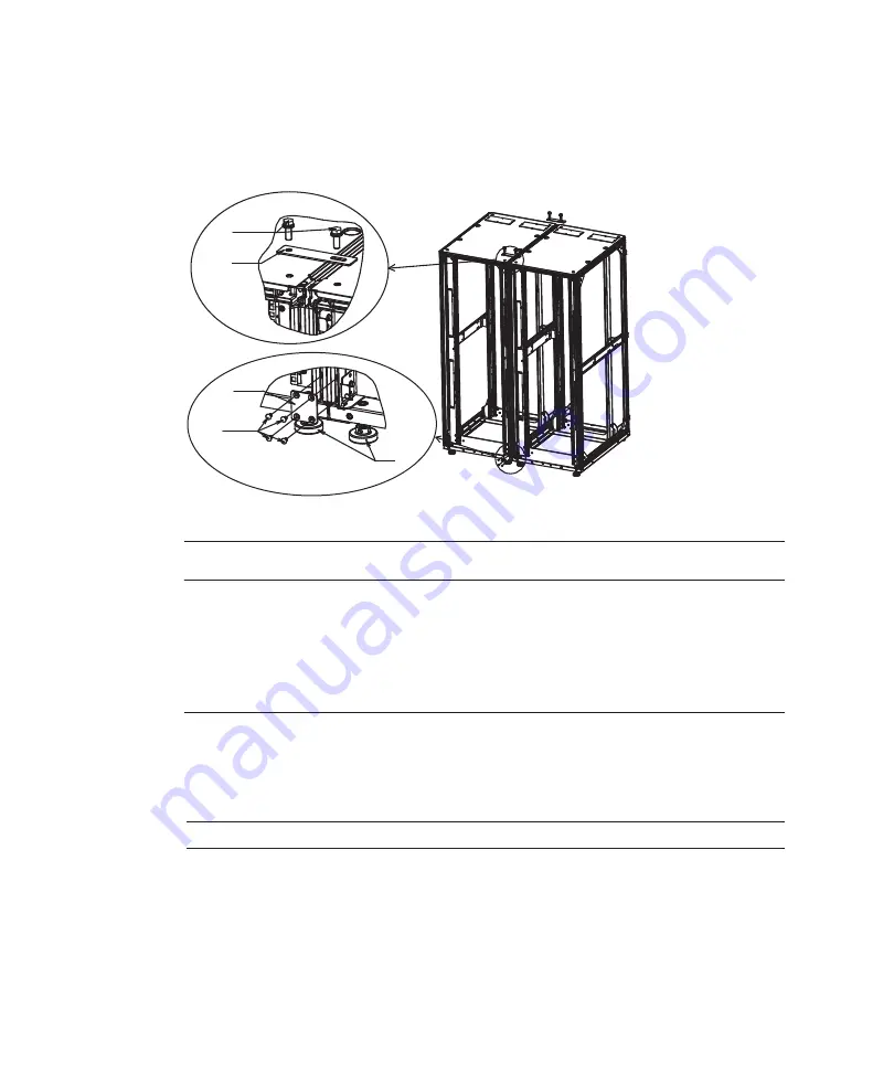
㩿㪉㪀
㩿㪈㪀
㩿㪊㪀
㩿㪋㪀
㩿㪌㪀
FRONT
Number
in
figure
Description
1
M12
hexagon
head
bolt
2
U
pper
connecting
bracket
3
Lower
connecting
bracket
4
M6
flat-head
screw
5
Leveling
foot
Note
-
Be
careful
when
attaching
the
side
plate
because
it
weighs
about
13
kg.
flat-head
screws.
c.
Finally,
tighten
the
M12
hexagon
head
bolts
for
securing
the
upper
connecting
brackets
that
have
temporarily
joined
the
racks.
Figure
3-23
Attaching
connecting
brackets
10.
Attach
the
side
plate
to
expansion
rack
2.
Attach
the
side
plate
removed
from
expansion
rack
1
with
the
10
screws
of
the
side
plate
removed
from
expansion
rack
1.
Fujitsu
M10/SPARC
M10
Systems
Installation
Guide
・
July
2015
94
Summary of Contents for M10 Series
Page 1: ...Fujitsu M10 SPARC M10 Systems Installation Guide Manual Code C120 E678 12EN July 2015 ...
Page 10: ...Fujitsu M10 SPARC M10 Systems Installation Guide July 2015 x ...
Page 156: ...Fujitsu M10 SPARC M10 Systems Installation Guide July 2015 142 ...
Page 176: ...Fujitsu M10 SPARC M10 Systems Installation Guide July 2015 162 ...
Page 208: ...Fujitsu M10 SPARC M10 Systems Installation Guide July 2015 194 ...
Page 240: ...Fujitsu M10 SPARC M10 Systems Installation Guide July 2015 226 ...
Page 252: ...Fujitsu M10 SPARC M10 Systems Installation Guide July 2015 238 ...
Page 290: ...Fujitsu M10 SPARC M10 Systems Installation Guide July 2015 276 ...
Page 310: ...Fujitsu M10 SPARC M10 Systems Installation Guide July 2015 296 ...
Page 336: ...Fujitsu M10 SPARC M10 Systems Installation Guide July 2015 322 ...
Page 368: ...Fujitsu M10 SPARC M10 Systems Installation Guide July 2015 354 ...
Page 374: ...Fujitsu M10 SPARC M10 Systems Installation Guide July 2015 360 ...


