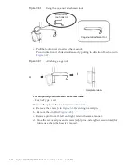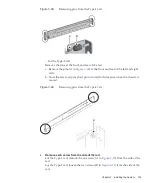
New
Reference: Old
New
(Dedicated to PCI
expansion unit)
Reference: Old
(Common to
M10-4/4S)
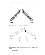
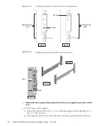
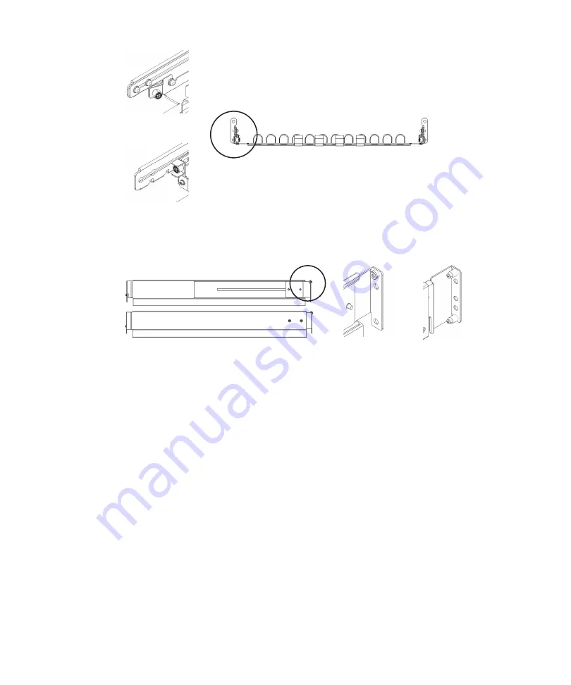
Figure
3-62
Type-2
cable
support
Figure
3-63
Type-2
rail
2.
Confirm
that
the
rack
is
fixed
in
place
to
prevent
the
rack
from
toppling
over.
For
details,
see
3.
Step
3
differs
depending
on
the
shape
of
the
supporting
column
holes
of
the
rack.
Perform
the
work
appropriate
to
the
shape
of
the
supporting
column
holes
of
the
rack.
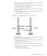
For
racks
with
supporting
columns
having
angled
holes
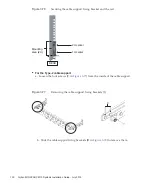
Attach
cage
nuts
to
the
left
and
right
supporting
columns
of
the
rack.
-
Attachment
locations
in
the
front
supporting
columns:
(From
the
bottom)
1U
center
and
2U
bottom
-
Attachment
locations
in
the
rear
supporting
columns:
(From
the
bottom)
1U
center
and
2U
center
Fujitsu
M10/SPARC
M10
Systems
Installation
Guide
・
July
2015
122
Summary of Contents for M10 Series
Page 1: ...Fujitsu M10 SPARC M10 Systems Installation Guide Manual Code C120 E678 12EN July 2015 ...
Page 10: ...Fujitsu M10 SPARC M10 Systems Installation Guide July 2015 x ...
Page 156: ...Fujitsu M10 SPARC M10 Systems Installation Guide July 2015 142 ...
Page 176: ...Fujitsu M10 SPARC M10 Systems Installation Guide July 2015 162 ...
Page 208: ...Fujitsu M10 SPARC M10 Systems Installation Guide July 2015 194 ...
Page 240: ...Fujitsu M10 SPARC M10 Systems Installation Guide July 2015 226 ...
Page 252: ...Fujitsu M10 SPARC M10 Systems Installation Guide July 2015 238 ...
Page 290: ...Fujitsu M10 SPARC M10 Systems Installation Guide July 2015 276 ...
Page 310: ...Fujitsu M10 SPARC M10 Systems Installation Guide July 2015 296 ...
Page 336: ...Fujitsu M10 SPARC M10 Systems Installation Guide July 2015 322 ...
Page 368: ...Fujitsu M10 SPARC M10 Systems Installation Guide July 2015 354 ...
Page 374: ...Fujitsu M10 SPARC M10 Systems Installation Guide July 2015 360 ...


