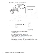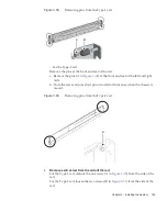
REAR
C
Note
-
If
the
dimension
between
the
front
and
rear
columns
of
the
rack
is
less
than
740
mm,
secure
the
cable
support
without
sliding
it
in
all
the
way.
The
fixing
location
varies
depending
on
the
dimension
between
the
front
and
rear
columns
of
the
rack.
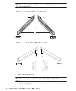
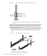
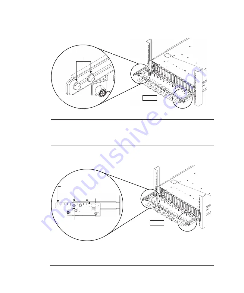
Based
on
align
the
scale
marks
(E
in
(spacing:
10
mm)
on
the
cable
support
with
the
screws
(F
in
of
the
fixing
brackets
to
secure
the
cable
support.
REAR
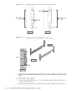
Scale position 1st
Scale position 10th
E
F
Scale
position 6th
Table
3-11
Dimensions
between
the
front
and
rear
columns
and
scale
positions
Dimension
between
front
and
rear
columns
(mm)
Scale
position
740
1st
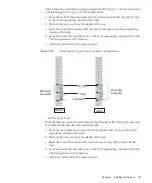
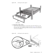
b.
Slide
in
the
cable
support
all
the
way,
and
tighten
the
four
screws
(C
in
).
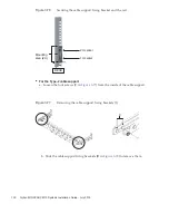
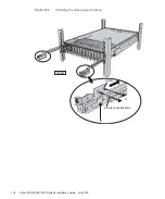
Figure
3-87
Attaching
the
cable
support
(2)
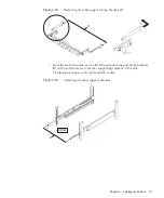
Figure
3-88
Attaching
the
cable
support
(3)
Fujitsu
M10/SPARC
M10
Systems
Installation
Guide
・
July
2015
138
Summary of Contents for M10 Series
Page 1: ...Fujitsu M10 SPARC M10 Systems Installation Guide Manual Code C120 E678 12EN July 2015 ...
Page 10: ...Fujitsu M10 SPARC M10 Systems Installation Guide July 2015 x ...
Page 156: ...Fujitsu M10 SPARC M10 Systems Installation Guide July 2015 142 ...
Page 176: ...Fujitsu M10 SPARC M10 Systems Installation Guide July 2015 162 ...
Page 208: ...Fujitsu M10 SPARC M10 Systems Installation Guide July 2015 194 ...
Page 240: ...Fujitsu M10 SPARC M10 Systems Installation Guide July 2015 226 ...
Page 252: ...Fujitsu M10 SPARC M10 Systems Installation Guide July 2015 238 ...
Page 290: ...Fujitsu M10 SPARC M10 Systems Installation Guide July 2015 276 ...
Page 310: ...Fujitsu M10 SPARC M10 Systems Installation Guide July 2015 296 ...
Page 336: ...Fujitsu M10 SPARC M10 Systems Installation Guide July 2015 322 ...
Page 368: ...Fujitsu M10 SPARC M10 Systems Installation Guide July 2015 354 ...
Page 374: ...Fujitsu M10 SPARC M10 Systems Installation Guide July 2015 360 ...

