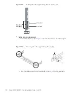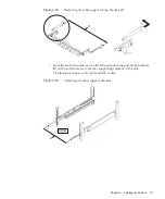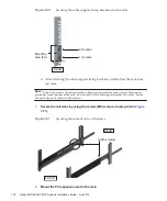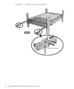
a.
Confirm
that
the
set
BB-ID
for
the
SPARC
M10-4S
mounted
at
the
very
bottom
of
the
rack
(BB#00)
is
00.
If
it
is
not
00,
set
it
to
00
with
a
thin,
pointed
instrument.
b.
Next,
set
01
for
the
BB-ID
of
the
SPARC
M10-4S
mounted
second
from
the
bottom
of
the
rack
(BB#01).
c.
Sequentially
set
BB-IDs
for
all
the
SPARC
M10-4S
units
while
checking
their
mounting
locations
in
the
rack.
Figure
4-1
BB-ID
switch
of
the
SPARC
M10-4S
2.
Check
the
BB-ID
settings
of
the
crossbar
boxes.
A
BB-ID
is
set
for
a
crossbar
box
when
shipped
from
the
factory.
Here,
check
the
mounting
locations
of
the
crossbar
boxes,
and
confirm
that
BB-IDs
80
to
83
are
set
sequentially.
If
a
setting
is
different,
change
the
setting
by
operating
the
BB-ID
switch
on
the
operation
panel
on
the
front
of
the
crossbar
box.
Fujitsu
M10/SPARC
M10
Systems
Installation
Guide
・
July
2015
144
Summary of Contents for M10 Series
Page 1: ...Fujitsu M10 SPARC M10 Systems Installation Guide Manual Code C120 E678 12EN July 2015 ...
Page 10: ...Fujitsu M10 SPARC M10 Systems Installation Guide July 2015 x ...
Page 156: ...Fujitsu M10 SPARC M10 Systems Installation Guide July 2015 142 ...
Page 176: ...Fujitsu M10 SPARC M10 Systems Installation Guide July 2015 162 ...
Page 208: ...Fujitsu M10 SPARC M10 Systems Installation Guide July 2015 194 ...
Page 240: ...Fujitsu M10 SPARC M10 Systems Installation Guide July 2015 226 ...
Page 252: ...Fujitsu M10 SPARC M10 Systems Installation Guide July 2015 238 ...
Page 290: ...Fujitsu M10 SPARC M10 Systems Installation Guide July 2015 276 ...
Page 310: ...Fujitsu M10 SPARC M10 Systems Installation Guide July 2015 296 ...
Page 336: ...Fujitsu M10 SPARC M10 Systems Installation Guide July 2015 322 ...
Page 368: ...Fujitsu M10 SPARC M10 Systems Installation Guide July 2015 354 ...
Page 374: ...Fujitsu M10 SPARC M10 Systems Installation Guide July 2015 360 ...

