B
A
A
A
Note
-
Do
not
pull
it
out
with
a
hold
on
the
cable.
Doing
so
prevents
the
connector
lock
from
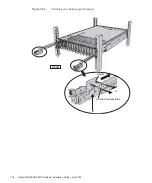
Figure
4-7
Removing
the
blank
panel
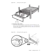
Figure
4-8
Mounting
the
crossbar
unit
2.
Move
the
crossbar
cables
(optical)
of
XBBOX#80/#81.
a.
Remove
the
crossbar
cables
from
L4
to
L7
and
from
R4
to
R7
of
crossbar
unit
#1
(see
).
Hold
the
tab
(A
in
of
the
crossbar
cable
(optical)
and
pull
it
straight
out
in
the
direction
of
the
arrow
to
remove
the
cable.
Chapter
4
Configuring
Building
Block
Connections
149
Summary of Contents for M10 Series
Page 1: ...Fujitsu M10 SPARC M10 Systems Installation Guide Manual Code C120 E678 12EN July 2015 ...
Page 10: ...Fujitsu M10 SPARC M10 Systems Installation Guide July 2015 x ...
Page 156: ...Fujitsu M10 SPARC M10 Systems Installation Guide July 2015 142 ...
Page 176: ...Fujitsu M10 SPARC M10 Systems Installation Guide July 2015 162 ...
Page 208: ...Fujitsu M10 SPARC M10 Systems Installation Guide July 2015 194 ...
Page 240: ...Fujitsu M10 SPARC M10 Systems Installation Guide July 2015 226 ...
Page 252: ...Fujitsu M10 SPARC M10 Systems Installation Guide July 2015 238 ...
Page 290: ...Fujitsu M10 SPARC M10 Systems Installation Guide July 2015 276 ...
Page 310: ...Fujitsu M10 SPARC M10 Systems Installation Guide July 2015 296 ...
Page 336: ...Fujitsu M10 SPARC M10 Systems Installation Guide July 2015 322 ...
Page 368: ...Fujitsu M10 SPARC M10 Systems Installation Guide July 2015 354 ...
Page 374: ...Fujitsu M10 SPARC M10 Systems Installation Guide July 2015 360 ...


